


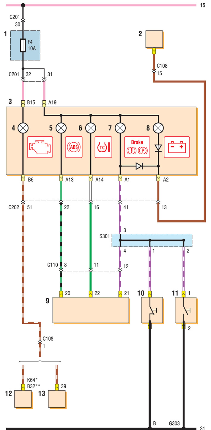
Instrument cluster wiring diagram (start): 1 - fuse box in the passenger compartment; 2 - generator; 3 - instrument cluster; 4 — Engine management system malfunction indicator; 5 — ABS malfunction indicator; 6 — Anti-slip system malfunction indicator; 7 — parking brake and brake system malfunction indicator; 8 — low battery indicator; 9 — ABS control unit; 10 — Parking brake indicator switch; 11 — brake fluid level sensor; 12 - ECU MR-140 or HV-240; 13 — Sirius D4 ECU
* ECU MR-140
** ECU HV-240
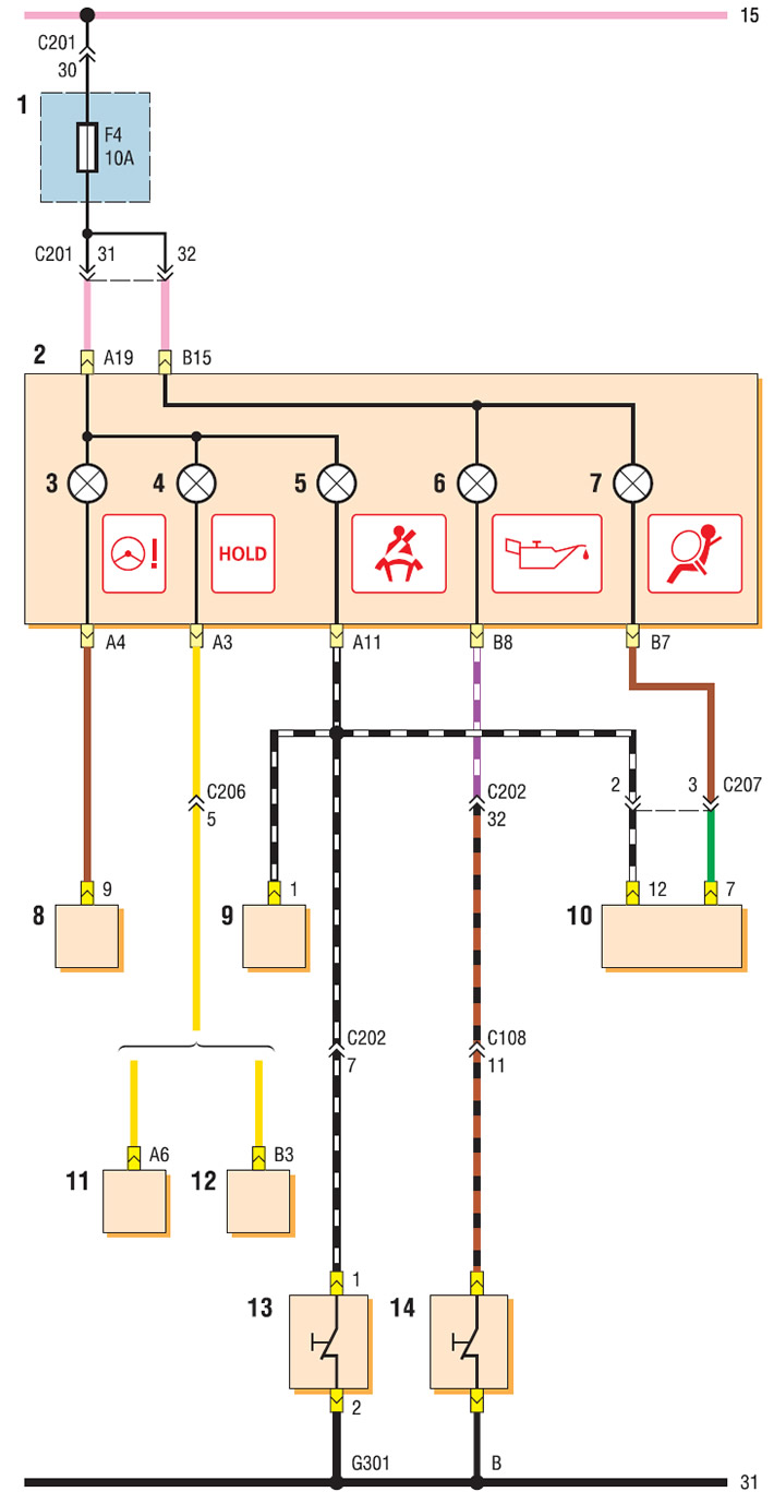
Instrument cluster wiring diagram (continuation): 1 - fuse box in the passenger compartment; 2 - instrument cluster; 3 — power steering malfunction indicator; 4 — "HOLD" mode activation indicator; 5 — Driver's seat belt indicator; 6 - low pressure indicator (emergency) engine oil pressure; 7 — Airbag malfunction indicator; 8 — power steering control unit; 9 - warning signal; 10 — airbag control unit; 11 — automatic transmission control unit (with ECU MR-140 or HV-240); 12 — automatic transmission control unit (with ECU Sirius D4);13 — Driver's seat belt indicator switch; 14 - oil pressure sensor
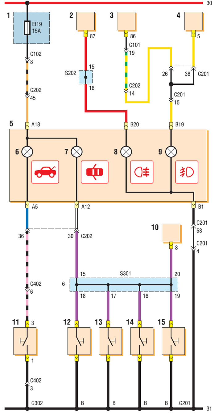
Instrument cluster wiring diagram (continuation): 1 - relay and fuse box in the engine compartment; 2 - Relay for switching on the fog light in the rear lights; 3 - fog light relay; 4 - fog light switch; 5 - instrument cluster; 6 — trunk lid open indicator; 7 - open door alarm; 8 — indicator of switching on of fog lamps in rear lights; 9 — fog light indicator; 10 — vehicle anti-theft system control unit; 11 — trunk light switch; 12 — ceiling light limit switch at the rear right door; 13 — ceiling light limit switch at the rear left door; 14 — ceiling light limit switch near the right front door; 15 — ceiling light limit switch near the left front door
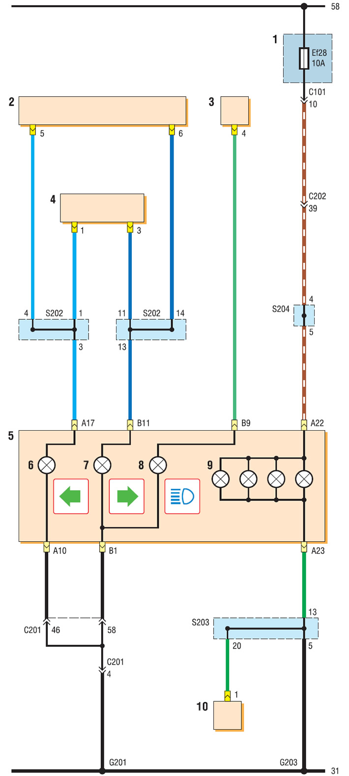
Instrument cluster wiring diagram (continuation): 1 - relay and fuse box in the engine compartment; 2 - hazard warning switch; 3 - headlight switch in the left steering column switch; 4 — direction indicator switch in the left steering column switch; 5 - instrument cluster; 6 — left turn signal indicator; 7 — Right turn signal indicator; 8 — high beam indicator; 9 — instrument lighting lamps; 10 — Instrument lighting brightness regulator
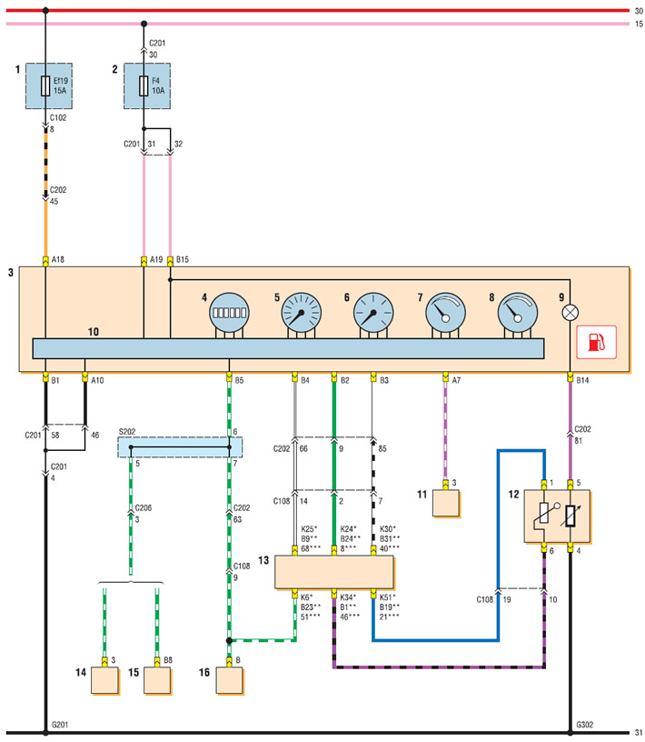
Instrument cluster wiring diagram (end): 1 - relay and fuse box in the engine compartment; 2 - fuse box in the passenger compartment; 3 - instrument cluster; 4 - odometer display; 5 - speedometer; 6 — tachometer; 7 — coolant temperature indicator; 8 — fuel level indicator; 9 — fuel reserve indicator; 10 — instrument cluster control unit; 11 - warning signal; 12 — fuel module; 13 — ECU; 14 - vehicle speed sensor (with ECU Sirius D4); 15 — automatic transmission control unit (with ECU MR-140 or HV-240); 16 - vehicle speed sensor (manual transmission)
* ECU MR-140
** ECU HV-240
*** ECU Sirius D4