
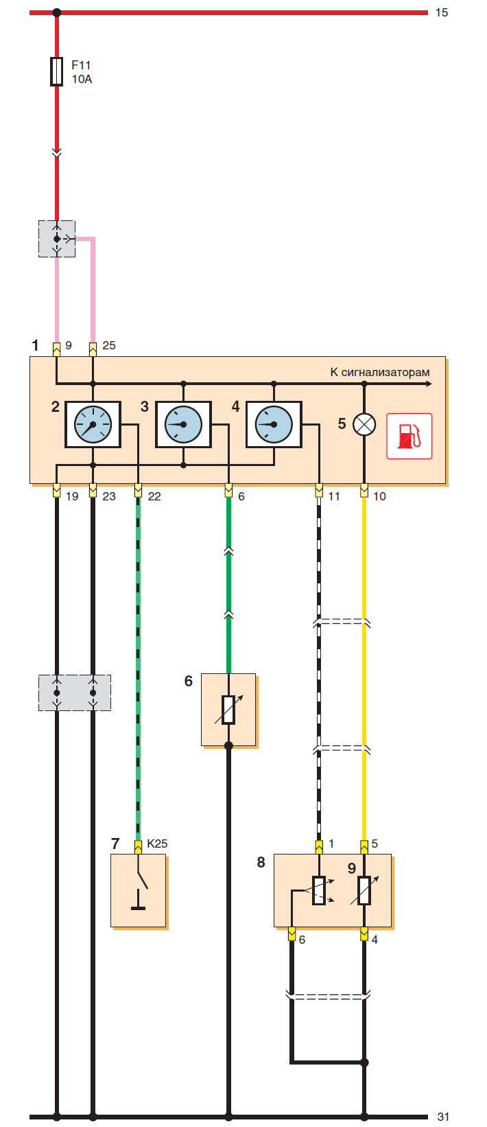
Instrument cluster wiring diagram (start): 1 - instrument cluster; 2 - tachometer; 3 - coolant temperature indicator; 4 - fuel level indicator; 5 - fuel reserve indicator; 6 - coolant temperature gauge sensor; 7 - ECU; 8 - fuel level indicator sensor; 9 - resistor (switch) fuel reserve indicator
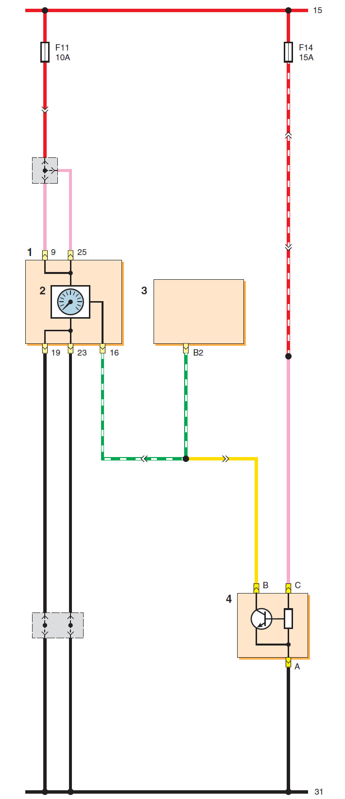
Instrument cluster wiring diagram (continuation): 1 - instrument cluster; 2 - speedometer; 3 - ECU; 4 - vehicle speed sensor
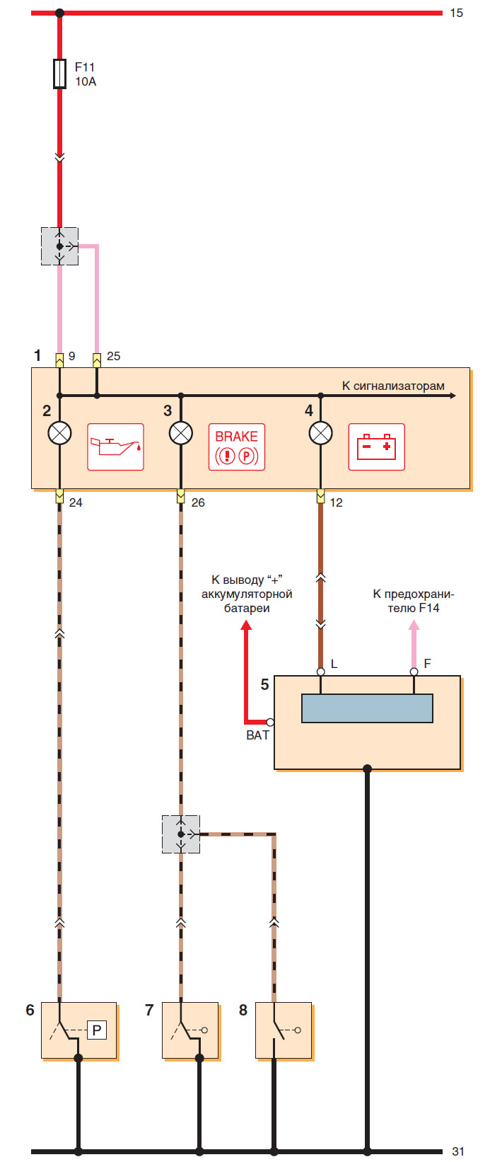
Instrument cluster wiring diagram (continuation): 1 - instrument cluster; 2 - low pressure indicator (emergency) engine oil pressure; 3 - parking brake and brake system malfunction indicator; 4 - Low battery indicator; 5 - generator; 6 - oil pressure sensor; 7 - Parking brake indicator switch; 8 - brake fluid level sensor
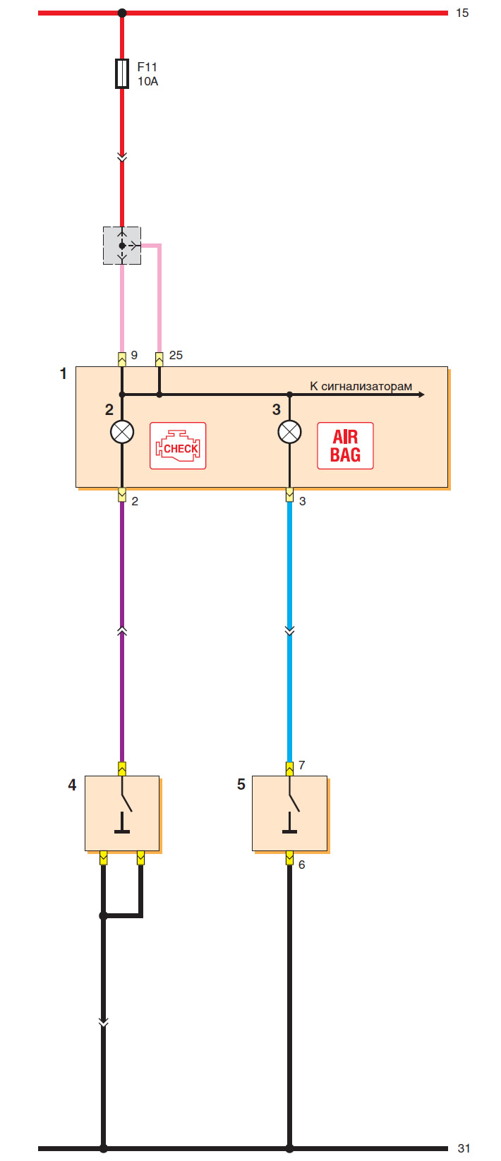
Instrument cluster wiring diagram (continuation): 1 - instrument cluster; 2 - Engine management system malfunction indicator; 3 - Airbag malfunction indicator; 4 - ECU; 5 - Airbag control unit
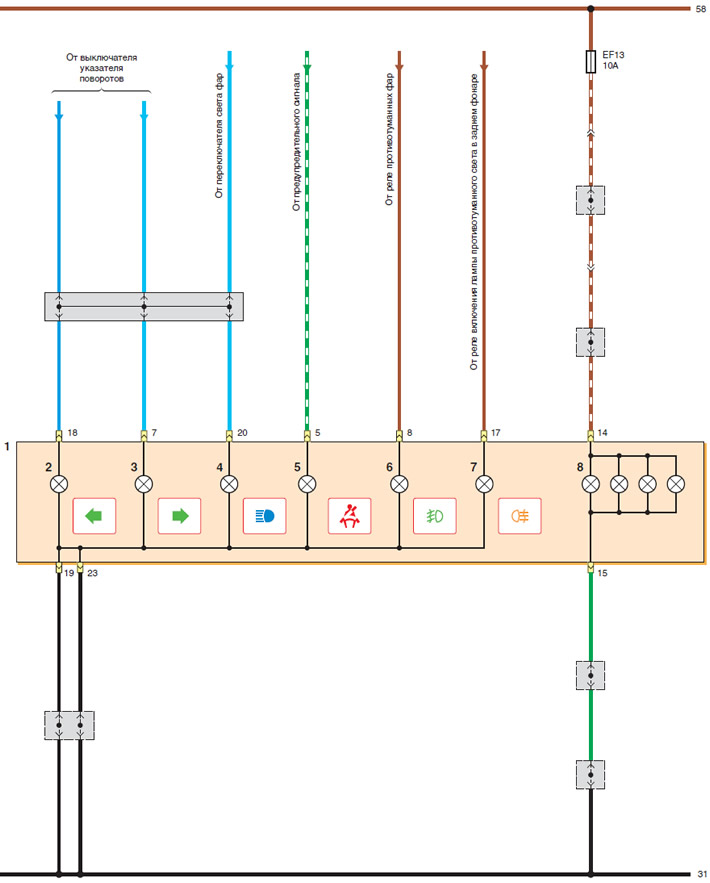
Instrument cluster wiring diagram (end): 1 - instrument cluster; 2 - left turn signal indicator; 3 - Right turn signal indicator; 4 - high beam indicator; 5 - Driver's seat belt indicator; 6 - fog light indicator; 7 - indicator of the fog light lamp in the rear light; 8 - Instrument lighting lamps
[The original article is on the website: chevyman]