
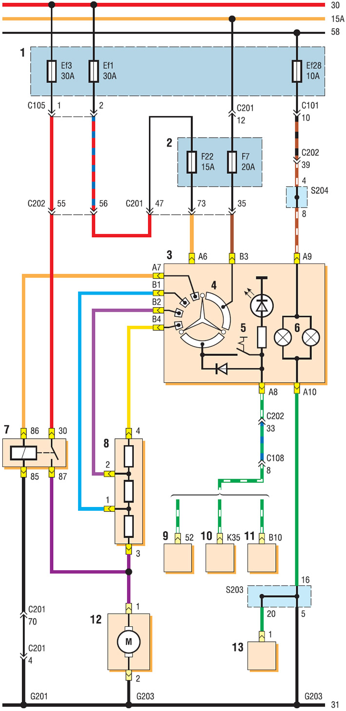
Connection diagram of the heating, ventilation and air conditioning system (start): 1 - relay and fuse box in the engine compartment; 2 - fuse box in the passenger compartment; 3 - ventilation, heating and air conditioning control unit; 4 — fan mode switch; 5 - air conditioner switch; 6 - backlight lamp; 7 — heater electric fan relay; 8 - additional fan motor resistor; 9 — Sirius D4 ECU; 10 — ECU MR-140; 11 — ECU HV-240; 12 — heater fan electric motor; 13 — Instrument lighting brightness regulator
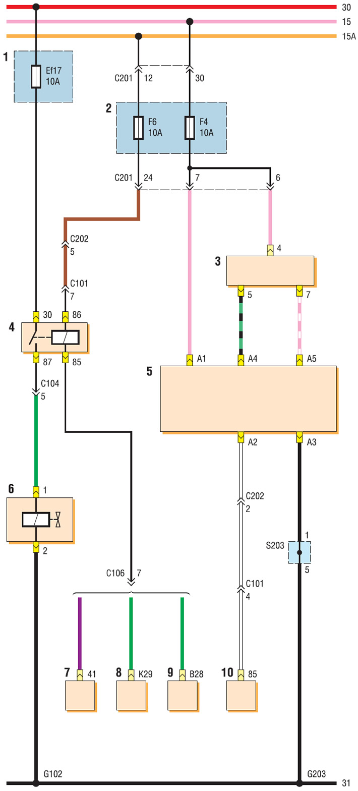
Connection diagram of the heating, ventilation and air conditioning system (end): 1 - relay and fuse box in the engine compartment; 2 - fuse box in the passenger compartment; 3 — recirculation flap drive electric motor; 4 - air conditioning compressor relay; 5 - ventilation, heating and air conditioning control unit; 6 — air conditioning compressor clutch; 7 — Sirius D4 ECU; 8 — ECU MR - 140; 9 — ECU HV-240; 10 — rear window heating relay
[The original text can be found on the website: «ChevyMan.ru»]