
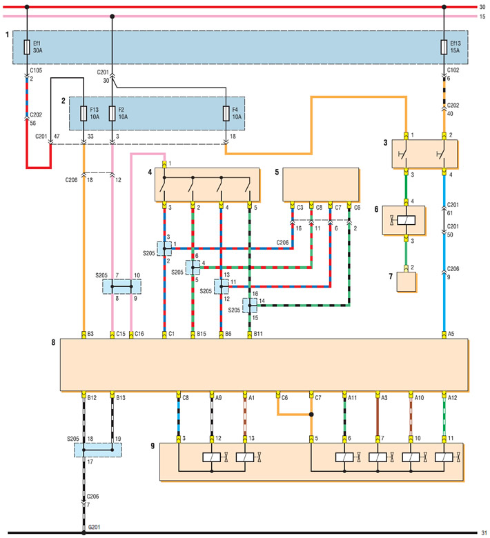
Automatic transmission electronic control system diagram (with ECU MR-140 or HV-240) (start): 1 - relay and fuse box in the engine compartment; 2 - fuse box in the passenger compartment; 3 - brake light switch; 4 — selector position sensor; 5 - instrument cluster; 6 — electromagnetic valve of the selector locking mechanism; 7 — selector position sensor "P"; 8 — automatic transmission control unit; 9 — valve mechanism of automatic transmission
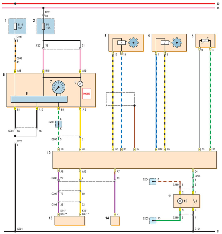
Automatic transmission electronic control system diagram (with ECU MR-140 or HV-240) (end): 1 - relay and fuse box in the engine compartment; 2 - fuse box in the passenger compartment; 3 — primary shaft speed sensor; 4 — secondary shaft speed sensor; 5 — working fluid temperature sensor; 6 - instrument cluster; 7 — speedometer; 8 — "HOLD" mode activation indicator; 9 — instrument cluster control unit; 10 — automatic transmission control unit; 11 — "HOLD" mode switch; 12 — switch illumination lamp; 13 — ECU; 14 — diagnostic connector
* with ECU MR-140
** with ECU HV-240