
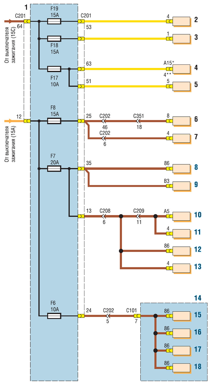
Wiring diagram of the fuse box in the passenger compartment (start): 1 - fuse box in the passenger compartment; 2 - cigarette lighter; 3 — socket; 4 - head unit for sound reproduction; 5 - hours; 6 — control regulator for electric drives of external mirrors; 7 — mirror folding control unit; 8 — heater fan relay (only with automatic air conditioning control); 9 - ventilation, heating and air conditioning control unit; 10 — automatic air conditioning control unit; 11 — electric motor for driving distribution flaps; 12 — High speed relay of the heater fan; 13 — recirculation flap drive electric motor; 14 - relay and fuse box in the engine compartment; 15 — air conditioning compressor relay; 16 — rear window heating relay; 17 — window lift relay; 18 — headlight relay
* with RDS function
** without RDS function
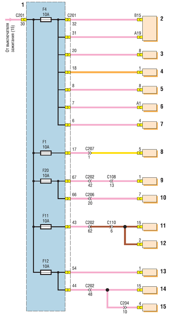
Wiring diagram of the fuse box in the passenger compartment (continuation): 1 - fuse box in the passenger compartment; 2 - instrument cluster; 3 - warning signal; 4 - brake light switch; 5 — power steering control unit; 6 - ventilation, heating and air conditioning control unit; 7 — recirculation flap drive electric motor; 8 — airbag control unit; 9 — Reverse light switch; 10 — automatic transmission selector position sensor (ECU MR-140 or HV-240); 11 — ABS control unit; 12 — ABS diagnostic connector; 13 — immobilizer control unit; 14 — vehicle anti-theft system control unit; 15 - rain sensor
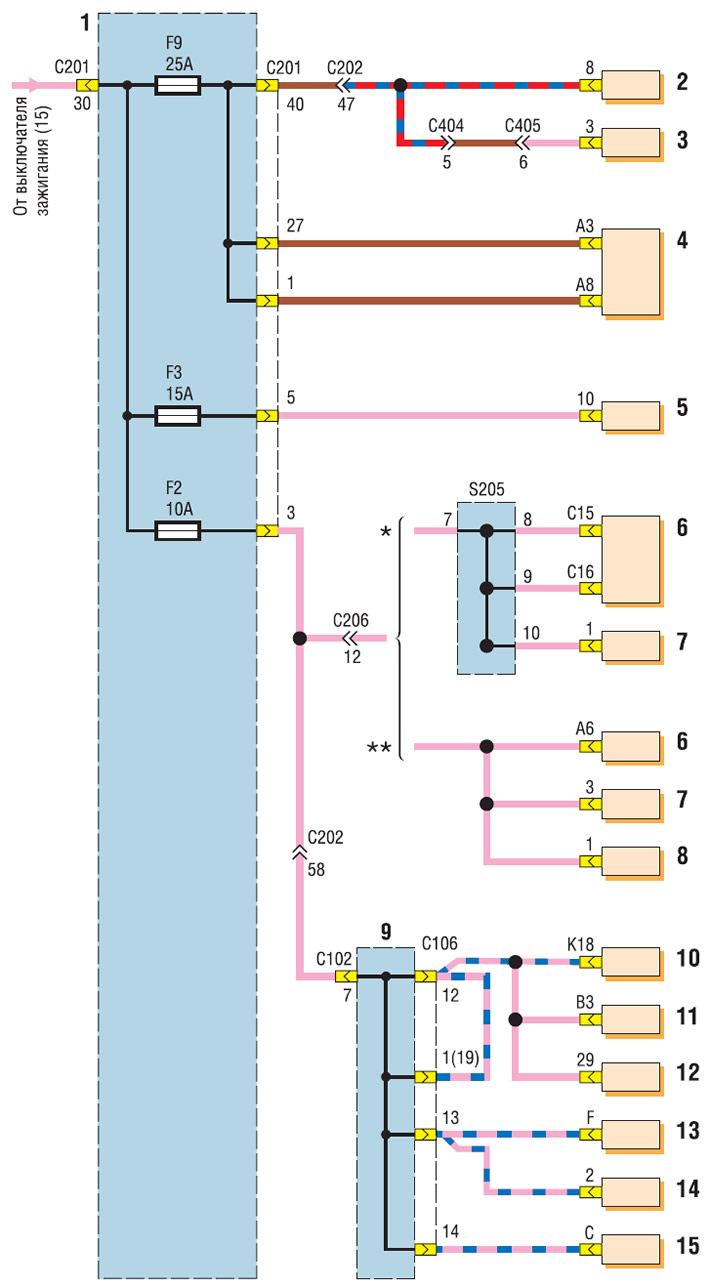
Wiring diagram of the fuse box in the passenger compartment (continuation): 1 - fuse box in the passenger compartment; 2 - Windshield wiper motor; 3 — Electric motor for the windshield wiper of the luggage compartment door; 4 - Right steering column wiper and washer switch; 5 - hazard warning switch; 6 — automatic transmission control unit; 7 — automatic transmission selector position sensor; 8 — vehicle speed sensor with automatic transmission; 9 - relay and fuse box in the engine compartment; 10 — ECU MR-140; 11 — ECU HV-240; 12 — Sirius D4 ECU; 13 — generator; 14 — electromagnetic valve of the intake manifold; 15 — vehicle speed sensor with manual transmission
* with ECU MR-140 and HV-240
** with Sirius D4 ECU
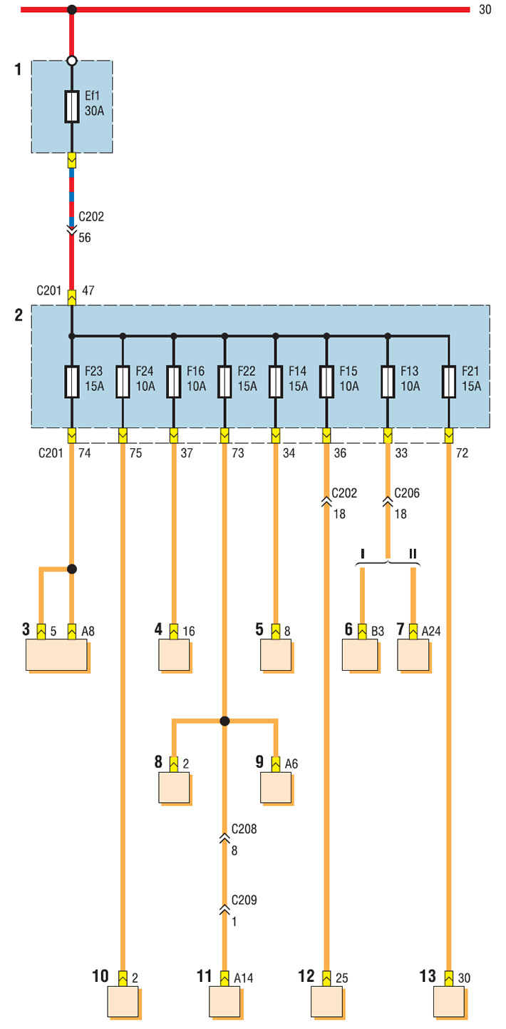
Wiring diagram of the fuse box in the passenger compartment (end): I - with ECU MR-140 or HV-240 II - with ECU Sirius D4; 1 - relay and fuse box in the engine compartment; 2 - fuse box in the passenger compartment; 3 - head unit for sound reproduction (without RDS function); 4 - diagnostic connector; 5 - hazard warning switch; 6 - automatic transmission control unit with 1.8 engine; 7 - automatic transmission control unit with 1.6 engine; 8 - immobilizer control unit; 9 - hours; 10 - automatic air conditioning control unit; 11 - Heating, ventilation and air conditioning control unit; 12 - vehicle anti-theft system control unit; 13 - Relay for switching on the fog light in the rear lights