
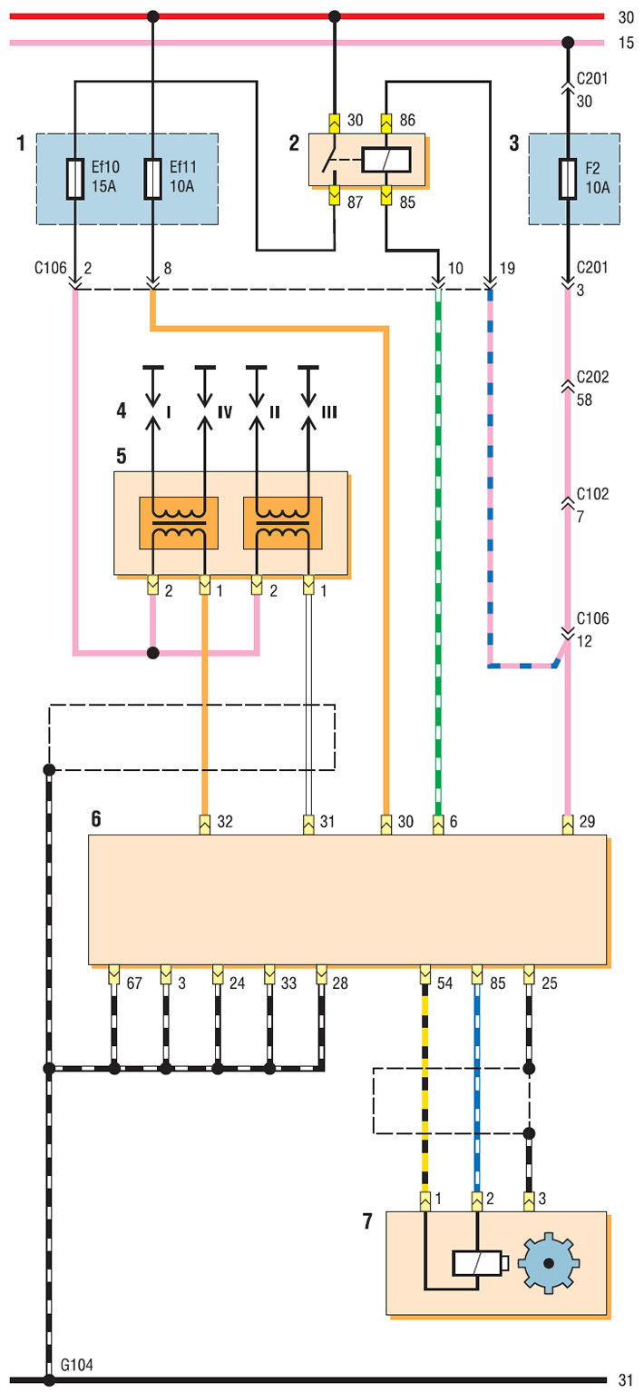
Schematic diagram of the electronic engine management system with the Sirius D4 control unit (start): 11 - relay and fuse box in the engine compartment; 2 — fuel pump and ignition coil power relay; 3 - fuse box in the passenger compartment; 4 - spark plugs; 5 - ignition coil; 6 — Engine control unit (ECU); 7 — crankshaft position sensor
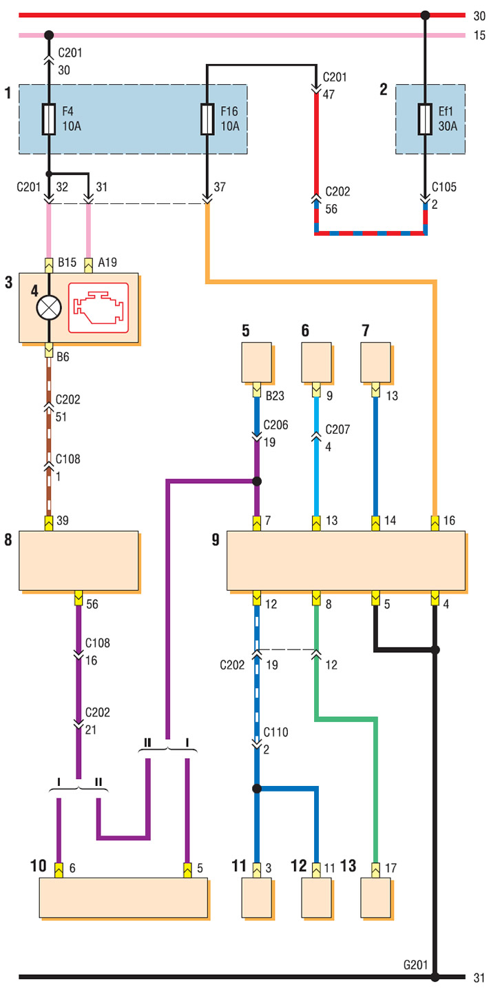
Electronic engine management system diagram with Sirius D4 control unit (continuation): I — with immobilizer; II - without immobilizer; 1 - relay mounting block in the passenger compartment; 2 - relay and fuse box in the engine compartment; 3 - instrument cluster; 4 — Engine management system malfunction indicator; 5 — automatic transmission control unit; 6 - Airbag control unit; 7 — power steering control unit; 8 — ECU; 9 — diagnostic connector; 10 — immobilizer control unit; 11 — ABS diagnostic connector; 12 — ABS control unit; 13 — vehicle anti-theft system control unit
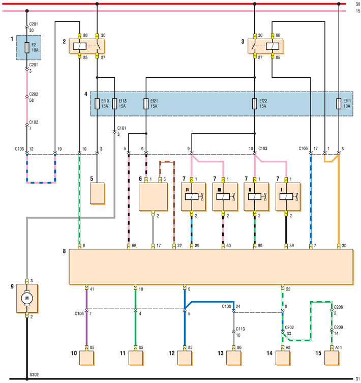
Electronic engine management system diagram with Sirius D4 control unit (continuation): 1 - fuse box in the passenger compartment; 2 — fuel pump and ignition coil power relay; 3 - main relay; 4 - relay and fuse box in the engine compartment; 5 — fuel line coupling; 6 — phase sensor; 7 - fuel injector; 8 — ECU; 9 — fuel module; 10 — air conditioning compressor relay; 11 — low speed relay of the cooling system fan; 12 — High speed cooling fan relay; 13 — control relay of the cooling system fan; 14 - ventilation, heating and air conditioning control unit; 15 — automatic air conditioning control unit
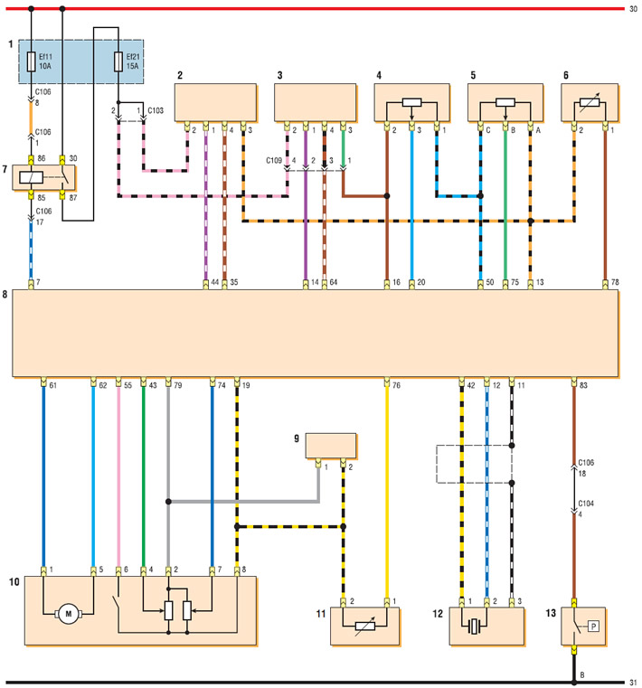
Electronic engine management system diagram with Sirius D4 control unit (with on-board diagnostics system) (continuation): 1 - relay and fuse box in the engine compartment; 2 - oxygen concentration control sensor; 3 - diagnostic oxygen concentration sensor; 4 - refrigerant pressure sensor; 5 - absolute air pressure sensor in the intake manifold; 6 - intake air temperature sensor; 7 - main relay; 8 — ECU; 9 — exhaust gas recirculation valve; 10 — idle speed control unit and throttle position sensor; 11 - coolant temperature sensor; 12 - knock sensor; 13 — power steering pressure sensor
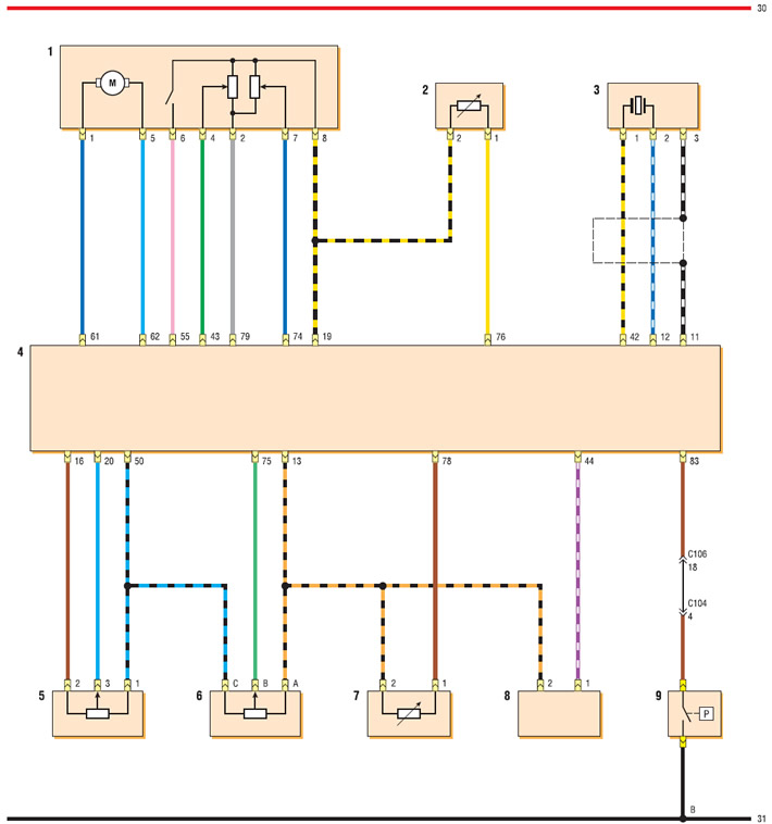
Electronic engine management system diagram with Sirius D4 control unit (without on-board diagnostics) (continuation): 1 — idle speed control unit and throttle position sensor; 2 - coolant temperature sensor; 3 - knock sensor; 4 — ECU; 5 - refrigerant pressure sensor; 6 - absolute air pressure sensor in the intake manifold; 7 - intake air temperature sensor; 8 - oxygen concentration sensor; 9 — power steering pressure sensor
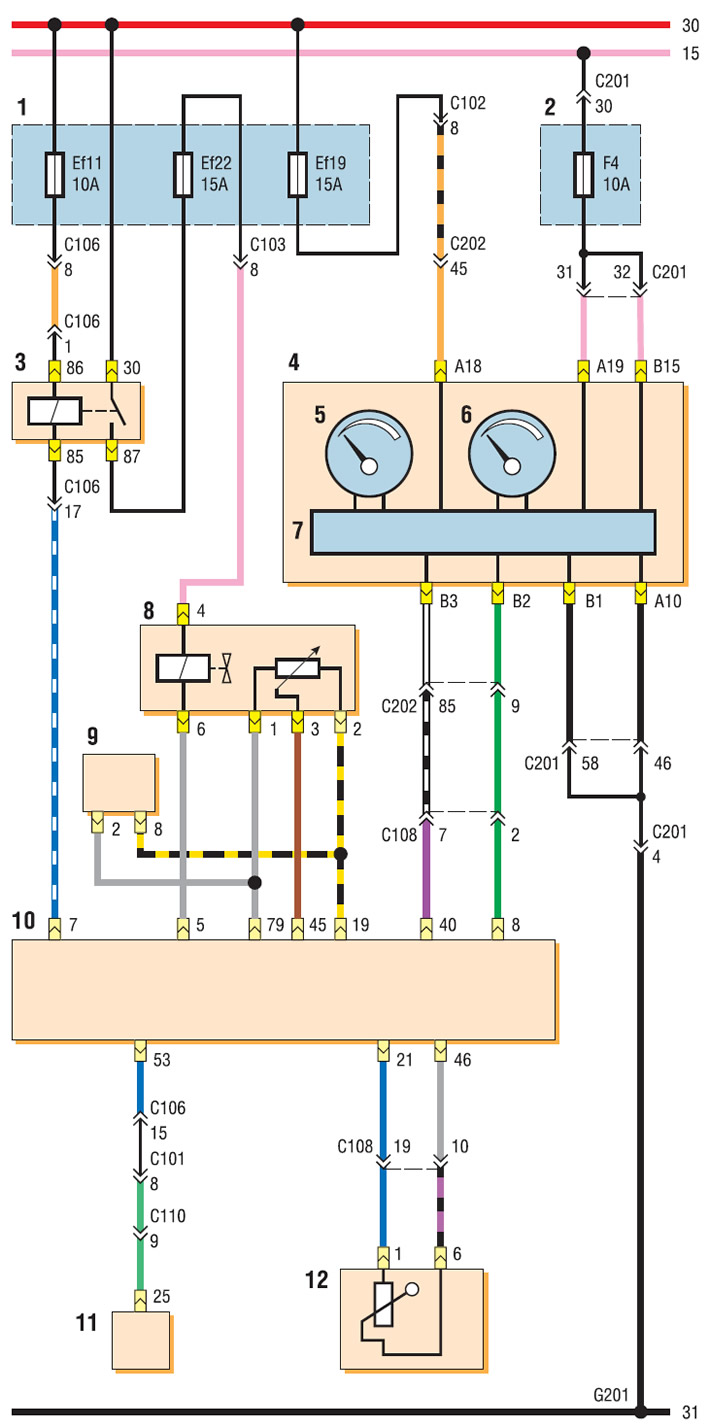
Electronic engine management system diagram with Sirius D4 control unit (EURO 3, with on-board diagnostics) (continuation): 1 - relay and fuse box in the engine compartment; 2 - fuse box in the passenger compartment; 3 - main relay; 4 - instrument cluster; 5 — fuel level indicator; 6 - coolant temperature indicator; 7 — instrument cluster control unit; 8 — exhaust gas recirculation valve; 9 — idle speed control unit and throttle position sensor; 10 — ECU; 11 — ABS control unit; 12 — fuel module
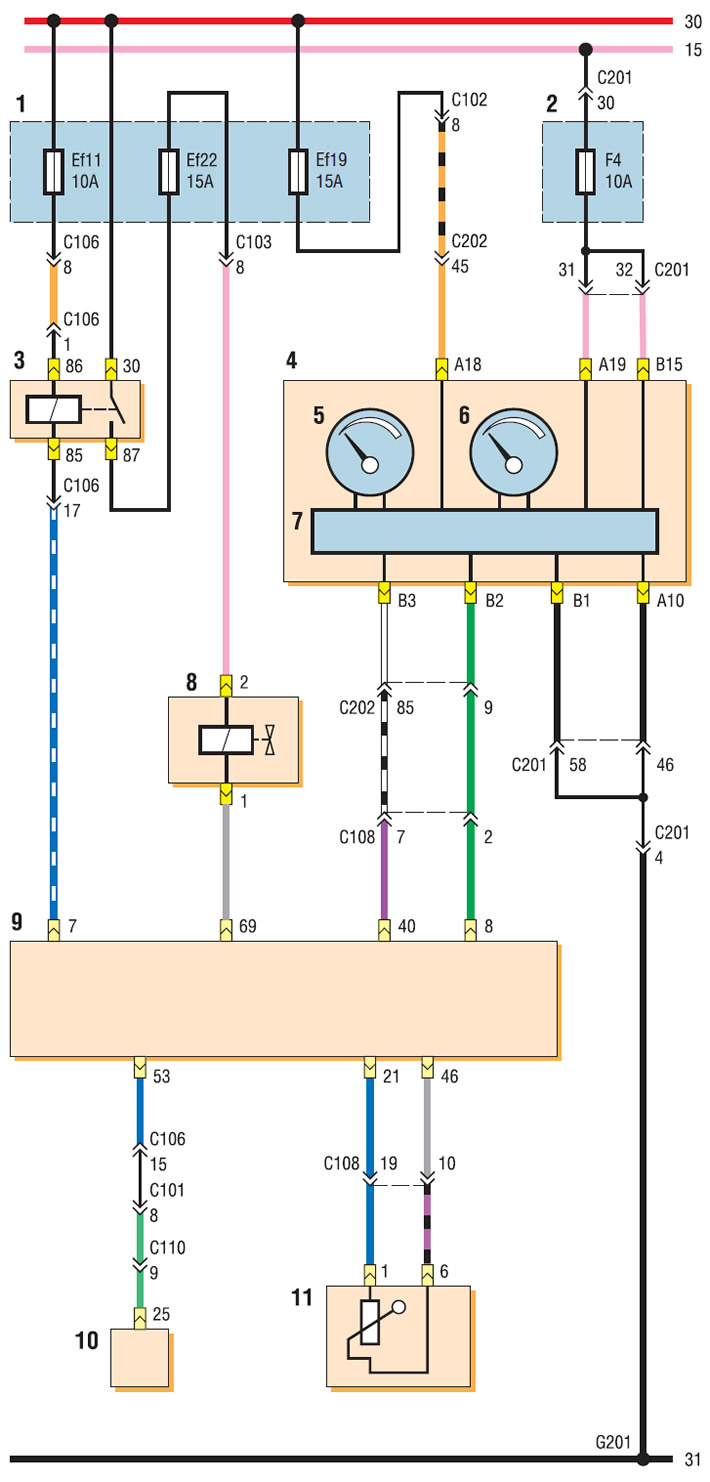
Electronic engine management system diagram with Sirius D4 control unit (without on-board diagnostics) (continuation): 1 - relay and fuse box in the engine compartment; 2 - fuse box in the passenger compartment; 3 - main relay; 4 - instrument cluster; 5 — fuel level indicator; 6 - coolant temperature indicator; 7 — instrument cluster control unit; 8 — exhaust gas recirculation valve; 9 — ECU; 10 — ABS control unit; 11 — fuel module
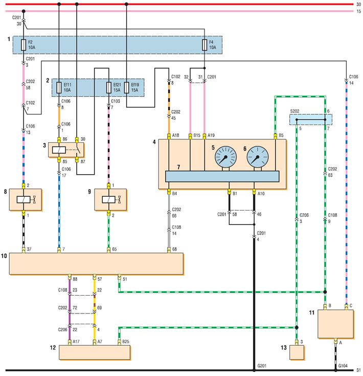
Schematic diagram of the electronic engine management system with the Sirius D4 control unit (end): 1 - fuse box in the passenger compartment; 2 - relay and fuse box in the engine compartment; 3 - main relay; 4 - instrument cluster; 5 - tachometer; 6 - speedometer; 7 — instrument cluster control unit; 8 — valve of the intake tract length variation system; 9 — purge valve of the adsorber; 10 — ECU; 11 — vehicle speed sensor with manual transmission; 12 — automatic transmission control unit; 13 — vehicle speed sensor with automatic transmission