
Removal the ECM/PCM unit
1. Electronic control unit ECM (control unit RCM) located in the car's interior under the dashboard (right side).
2. Disconnect the wires from the battery.
3. Unscrew the screws securing the decorative panel under the right side of the instrument panel.
4. Remove the decorative panel, thus opening access to the switch panel (see illustration).
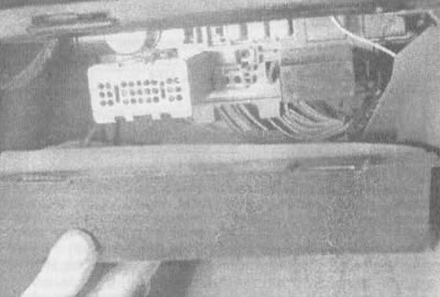
3.4 Remove the lower trim panel under the glove box, revealing access to the switch panel and ECM/PCM unit
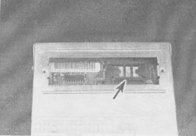
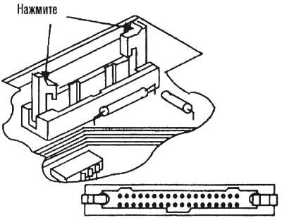
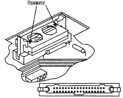
5. Disconnect both electrical connectors from the ECM/PCM (see illustration).
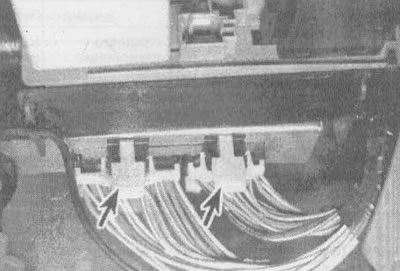
3.5. Press firmly on the plates (shown by arrows) to disconnect electrical connectors from the ECM/PCM unit
Caution: When disconnecting and connecting electrical connectors, turn off the ignition to prevent damage to the ECM/PCM.
6. Unscrew the fastening nut (see illustration) on the left side of the ECM/PCM.
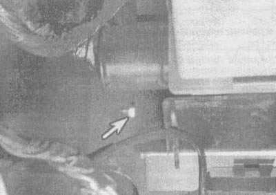
3.6. Unscrew the fastening nut (shown by arrow) computer to the holder
7. Carefully slide the ECM/PCM downward to expose the fuse panel.
Caution: To prevent damage to your computer from static electricity, wear gloves and use a special anti-static pad to store the ECM/PCM after removal.
General description
EPROM (3.1L engine)
8. To ensure that the same ECM model can be used on different vehicles (see illustration), use a device called a EPROM (programmable read-only memory). To access the EPROM, you must remove the cover. The EPROM is located inside the ECM unit (see illustration) and contains information about the vehicle's weight, engine, transmission, final drive ratio, etc. An ECM with a specific serial number can be used in many General Motors (GM) vehicles, but each ECM can only be used in the vehicle for which it was designed. In this regard, it is necessary to check the latest editions of spare parts catalogs and service bulletins to clarify information about the serial numbers of the EPROMs when replacing them. The ECM is usually purchased without a ROM. It is necessary to carefully remove the ROM chip from the old ECM and install it on the new ECM.
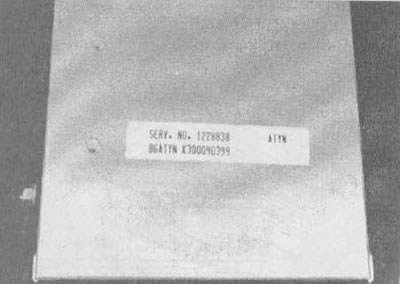
3.8a. If you are replacing the ECM, compare the service numbers on the labels of the new and old ECM |
3.8b. EPROM position (shown by arrow) in the ECM unit for the 3.1 L engine (the PCM unit for the 3.8 L engine is designed similarly, only instead of the EPROM and CALPAK, the MEM-CAL device is installed |
CALPAK (3.1L engine)
9. A device called CALPAK is used to ensure fuel supply in case of failure of other ECM components. If CALPAK fails, a new ECM must be installed.
MEM-CAL (3.8L engine)
10. The MEM-CAL device includes the functions of the EPROM, CALPAK, and ESC unit used in other General Motors vehicles. Like the EPROM, it contains the calibration information for the vehicle, as well as an emergency fuel control circuit in the event of failure of other PCM components.
Replacement of elements
EPROM (3.1L engine)
11. Turn the ECM over with the bottom cover facing up and place it on a clean work surface.
12. Remove the protective cover of the EPROM/CALPAK.
13. Using a ROM removal tool, pry the ROM holder from the narrow ends (see illustration). Rock the holder slightly from side to side and pull it upward. The EPROM together with the holder should easily come out of the socket.
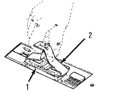
3.13. Using a device for removing the EPROM, hook the EPROM holder from the narrow ends and gently rock the device with the holder until the EPROM comes out of the socket: 1 - EPROM holder, 2 - EPROM extraction tool
Attention! The EPROM holder must be removed only using a special device. Removal without this device or using other devices may result in damage to the ROM chip or its socket.
14. Before putting the EPROM holder aside, remember its position when installed (see illustration).
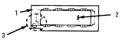
3.14. Remember the relative orientation of the notch on the EPROM and the smaller notch on the holder: 1 - EPROM holder, 2 - EPROM, 3 - notch in EPROM matches small notch in holder and mark
15. If you are replacing the ECM, remove the new ECM from its holder, check its service number and make sure it matches the number on the old ECM (see illustration 3.8a).
16. If you are replacing a ROM, remove the new ROM from its holder, check its service number and make sure it matches the number on the old ROM.
17. Position the "EPROM/EPROM holder" block perpendicular to the socket so that the notch on the holder is aligned with the notch in the socket on the side of the 1st contact. Press the EPROM holder until it fits snugly into place (see illustration).
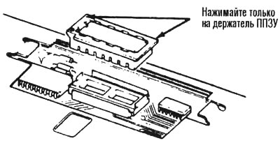
3.17. Only apply pressure to the ends of the EPROM holder - pressing on the inner area may bend or break the contact pins or cause the EPROM to fail
18. When installing a new EPROM, make sure that the notch on it is aligned with the small notch on the holder.
Attention: If the EPROM is installed the wrong way round, it will fail when the ignition is turned on.
19. Using the special tool, install the new EPROM holder into the EPROM socket in the ECM. The notch on the holder must be aligned with the notch in the socket. Press down on the EPROM holder until it fits snugly.
Attention! Do not press on the EPROM chip - only on the holder.
20. Install the protective cover on the ECM and tighten the two screws.
21. Install the ECM unit on the bracket, connect the electrical connectors to it and install it under the instrument panel.
22. Start the engine.
23. Set the diagnostic mode by connecting the ALDL diagnostic terminal to ground (see section 2). If no fault codes are displayed, the EEPROM is installed correctly.
24. If fault code 51 is displayed or the light comes on and stays on "SERVICE ENGINE SOON", then this may be due to incomplete seating of the EPROM, installation of the EPROM in the reverse position, bending of the contact pins, or a faulty EPROM.
25. If the fault is caused by the EPROM not being seated completely, it can be corrected by pressing firmly on both ends of the holder.
26. If the contacts of the microcircuit are bent, remove the EPROM, straighten the contacts and reinstall the EPROM. If you break a contact while straightening, the EPROM must be replaced with a new one.
27. If a thorough check has shown that the EPROM is tightly seated, installed correctly and the contacts are not bent, and the lamp "SERVICE ENGINE SOON" continues to burn, the EPROM is most likely faulty and should be replaced.
MEM-CAL (3.8L engine)
Note: In terms of removing the PCM from the vehicle, the procedures for replacing the MEM-CAL are the same as those for the EPROM. However, the procedures for removing and installing the MEM-CAL, as well as the functional check of its correct installation, are slightly different from those for the EPROM and CALPAK.
28. Remove the MEM-CAL protective cover.
29. Using two fingers, spread both clamps of the MEM-CAL apart (see illustration). Simultaneously grasp the MEM-CAL by both ends and pull it out of the socket. Do not remove the MEM-CAL unit cover.
3.29. Move both clamps apart (shown by arrows) from the MEM-CAL unit and simultaneously grasp the unit by both ends and remove it from the socket
Caution: Using other methods of removal and installation may damage the MEM-CAL unit or its socket.
30. Make sure that the numbers on the old and new PCM match (or the numbers on the old and new MEM-CAL, depending on what you are replacing), as described for removing and installing the EPROM (see illustration 3.8a).
31. To install the MEM-CAL unit into the socket, press on its ends.
32. The notches on the MEM-CAL must be aligned with the notches 8 in the MEM-CAL connector. Press the ends of the MEM-CAL until both clips snap onto the edges of the MEM-CAL. Do not press on the middle of the block - only on its edges (see illustration).
3.32. To install the MEM-CAL unit, press only on the ends (shown by arrows). Make sure the notches on the MEM-CAL match the notches in the socket
33. The remaining installation operations are the same as for the EPROM.
34. After the new MEM-CAL unit is installed in the old PCM (or the old MEM-CAL is installed in the new PCM), check the correct installation by following these steps:
- a) Turn on the ignition.
- b) Set the diagnostic mode to ALDL (see section 2).
- c) Wait until code 12 is displayed 4 times to make sure there are no other codes. This indicates that the MEM-CAL is installed correctly and the PCM is working properly.
35. If codes 41, 42, 43, 51 are displayed or the lamp lights up and stays on "SERVICE ENGINE SOON", then this may be due to incomplete seating or a malfunction of the MEM-CAL unit. If the MEM-CAL unit is not seated tightly, press hard on its edges. If it is necessary to remove the MEM-CAL unit, follow the instructions above.