
General description and verification
9. Oxygen sensor located in the exhaust manifold (see illustration), carries out current monitoring of the oxygen content in the exhaust gases. The oxygen contained in the exhaust gases interacts with the oxygen sensor, resulting in an output voltage that varies from 0.1 V (high oxygen, lean mixture) up to 0.9 V (low oxygen, rich mixture). The ECM/PCM continuously analyzes this voltage to determine the air/fuel mixture ratio. The ECM/PCM changes the fuel/air ratio by controlling the pulse width (opening time) fuel injectors. The ideal ratio in terms of minimizing harmful emissions and maximizing catalyst efficiency is a ratio of 14.7 parts air to one part fuel. It is this ratio that the ECM/PCM unit, together with the oxygen sensor, tries to constantly maintain.
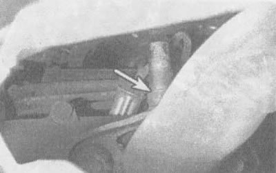
4.9. Before removing the oxygen sensor from the exhaust manifold, make sure the engine is completely cool
10. The oxygen sensor does not produce an output voltage if its temperature is below the normal operating temperature of approximately 320°C. During the initial warm-up period of the engine, the ECM/PCM operates in open loop mode.
11. If the engine warms up to normal operating temperature and/or runs for two minutes or more and if the oxygen sensor produces a constant signal voltage between 0.35-0.55 V even when the TPS indicates that the engine is not idling, the ECM/PCM will set code 13.
12. A delay of 2 minutes or more between engine start and normal sensor operation accompanied by a low voltage signal or a short in the sensor circuit will cause the ECM/PCM to set code 44. If a high voltage signal is generated, the ECM will set code 45.
13. When one of the above codes is set, the ECM/PCM operates in open loop mode, i.e. fuel delivery is controlled based on the programmed mode rather than using information from the oxygen sensor.
14. Correct operation of the oxygen sensor depends on four conditions:
- a) Electrical. The low voltages generated by the sensor depend on good, clean electrical connections, which should be checked whenever there is any suspicion or indication that the sensor is not operating properly.
- b) Supply of outside air. The design of the sensor is such that gases circulate inside it. In all cases of removal, installation or replacement of the sensor, check that the channels are not clogged.
- c) Normal operating temperature. The ECM/PCM will not respond to the sensor signal until the sensor reaches approximately 320°C. This factor must be taken into account when evaluating the sensor performance.
- d) Unleaded (tetraethyl lead free) gasoline. For the sensor to function properly, unleaded fuel must be used.
15. In addition to the above conditions, special care must be taken when servicing the sensor in any way.
- a) The oxygen sensor has a non-removable flexible lead with an electrical connector, which must not be disconnected from the sensor. Damage to or disconnection of the flexible lead or electrical connector from the sensor may adversely affect the operation of the sensor.
- b) It is necessary to clean the electrical connector of the sensor and its slotted tail from traces of grease, dirt and other foreign substances.
- c) Do not use any solvents to clean the oxygen sensor.
- d) Do not drop the sensor and handle it with care.
- d) To avoid melting the silicone case material and to ensure normal operation of the sensor, pay attention to the correct installation of the case.
Replacement
Note: Since the oxygen sensor is mounted in the exhaust manifold or tailpipe, which contracts when cooled, it can be difficult to remove from a vehicle with a cold engine. Therefore, to avoid the risk of damaging the sensor (if you plan to reinstall it into a new manifold or exhaust pipe) start the engine and let it run for a minute or two, then turn it off and proceed to remove the sensor. When performing work, try not to touch hot parts to avoid burns.
16. Disconnect the cable from the negative terminal of the battery.
17. After raising the vehicle, securely place it on stands.
18. After loosening the latch, carefully disconnect the electrical connector from the sensor.
19. Carefully unscrew the sensor from the exhaust manifold.
Caution: Applying excessive force may damage the threads on the sensor body.
20. To make it easier to remove the sensor next time, apply a compound to its threads that prevents corrosion. The threads on a new sensor are pre-coated with this compound at the manufacturing plant; however, if you intend to reuse a sensor removed from a vehicle, renew the coating.
21. After screwing the sensor into the manifold, tighten it securely. Connect the electrical connector on the pigtail to the main wiring harness on the engine.
22. Lower the vehicle to the ground and connect the cable to the negative terminal of the battery.
(The original article can be found on the resource: CHEVYMAN.ru)