
General description
74. The crankshaft position sensor is mounted on an aluminum bracket and is attached to the front left side of the timing chain cover. It is partially located behind the anti-vibrator (see illustration). A four-pin connector with wiring connecting it to the ignition unit is attached to the sensor body. The dual Hall effect crankshaft position sensor contains two switches with one common magnet mounted between them. The magnet is separated from each switch by an air gap. The anti-vibrator is equipped with induction rings that provide the creation of a sequence of "ON-OFF-ON" pulses necessary for setting the synchronization of the ignition advance sequence. Although there is no spark advance procedure for the Direct Ignition System (DIS) circuit, knowing the crankshaft position is still important for it. The sensor must not come into contact with the interrupter rings, as this may damage it, causing the engine to stall.
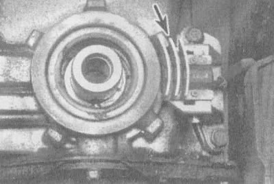
4.74. Crankshaft position sensor (shown by arrow); for greater clarity, the anti-vibrator has been removed from the engine
Examination
75. To check the functionality of the crankshaft position sensor, a special device from General Motors is needed (diagnostic computer Tech 1 N94-00101 A). Therefore, the sensor should be taken to a repair shop.
Replacement
76. Disconnect the cable from the negative terminal of the battery.
77. Remove the poly V-belt (see chapter 1, section 21).
78. Raise the vehicle and support it securely on stands.
79. After removing the right front wheel, remove the cover from the wing.
80. Disconnect the electrical connector from the crankshaft position sensor (see illustration).
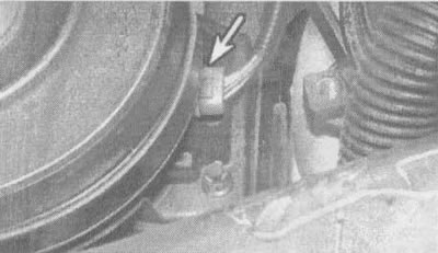
4.80. Disconnect the electrical connector from the crankshaft position sensor (shown by arrow)
81. After unscrewing the bolt, remove the crankshaft anti-vibration device (see Chapter 2, Part B, Section 11).
82. Remove the crankshaft position sensor protective screen from the timing chain cover. When disconnecting the sensor using a lever or other sharp tool, be careful not to damage it.
83. After unscrewing the bolts, disconnect the crankshaft sensor from the chain cover.
84. The sensor is installed in the reverse order.
Adjustment
85. Install the crankshaft sensor to the base, but do not secure it.
86. Position the sensor properly with the base attached to the special fixture (see illustration), on the timing chain cover.
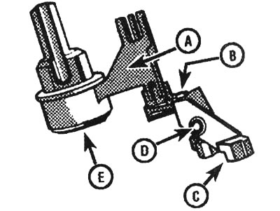
4.86. Install the special adjusting device on the base, but do not tighten the bolt: A - special device J-37089, B - sensor, C - base, D - bolt, E - crankshaft
87. The other end of this device (see illustration) place on the crankshaft.
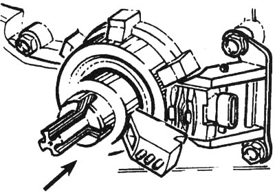
4.87. Slide special tool J-37089 onto the crankshaft end to install the sensor, then tighten its mounting bolts
88. Using bolts, attach the base to the cylinder block and tighten to 30-35 ft-lbs.
89. After tightening the base clamp bolt to 30-35 ft-lbs, remove the special tool (J-37089).
90. Install the crankshaft position sensor shield.
91. After installing the special device J-37089 on the anti-vibrator, rotate it very slowly (see illustration). If the device touches the anti-vibrator at any point, replace the anti-vibrator with a new one.
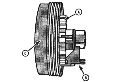
4.91. Install the special device on the anti-vibrator and check the induction rings for deflections or other damage: A - induction rings, B - special device J-37089, C - anti-vibrator
92. Install the anti-vibration device on the crankshaft.
93. After screwing in the anti-vibration mounting bolt, tighten it to the torque specified in the technical data in chapter 2, Section 2.2.
94. The remaining operations for installing the crankshaft position sensor are performed in the reverse order.