
Attention! The antivibrator is serviced when assembled. Do not attempt to separate the pulley from the balancer hub.
1. Disconnect the cable from the negative terminal of the battery.
2. Loosen the right front wheel nuts.
3. Raise the vehicle and support it securely on stands.
4. Remove the front right wheel.
5. Remove the front right inner mudguard (see illustration).
6. Remove the drive belt (see chapter 1, section 21).
7. Remove the lower flywheel cover (see illustration) and insert the blade of a large screwdriver between the teeth of the ring gear to prevent the crankshaft from turning while your assistant loosens the crankshaft balancer mounting bolt (see illustration). Usually the bolt is tightened quite tightly, so use a socket wrench with a socket insert.
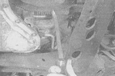
11.7a. Insert a large screwdriver between the teeth of the flywheel and lock the crankshaft |
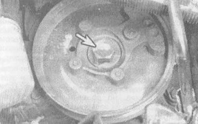
11.7b. Loosen the bolt in the center of the anti-vibrator hub (indicated by the arrow) |
8. The anti-vibrator is pulled out of the crankshaft by hand. Leave the woodruff key in place on the crankshaft end.
9. The unit is installed in the reverse order. Align the keyway with the woodruff key (see illustration), do not bend the metal antennae. Do not forget to apply a layer of universal grease to the contact surface of the rear side of the anti-vibrator with the seal (otherwise, the sealing lip may be damaged, which will lead to oil leakage).

11.9. Don't forget to align the keyway (indicated by the arrow) with crankshaft key
10. Apply thread sealant to the threads and tighten the crankshaft bolt to the torque specified in the specifications given in this chapter.
11. The remaining parts are installed in the reverse order.
[The text of the article was obtained from the website «CHEVYMAN.ru»]