
Caution: Allow the engine to cool completely before starting this operation.
Note: Exhaust system components are often difficult to remove - they are burnt due to the repeated heating and cooling cycles they are constantly subjected to. To facilitate removal, apply penetrating compound to all threads of exhaust manifold and exhaust pipe mounting parts and allow it to soak in.
Front manifold
1. Disconnect the cable from the negative terminal of the battery.
2. To gain access to the manifold, remove the cooling fan (see chapter 3, section 4).
3. Unscrew the bypass valve from the flange (U-shaped) pipes fastening bolts (see illustration).
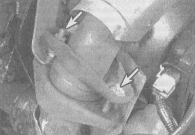
9.3. The exhaust manifold pipes are secured to the exhaust pipe with bolts (shown by arrows)
4. Loosen the oil level dipstick tube mounting nut and unscrew the dipstick tube from the block.
5. Remove the wires from the front spark plugs (see chapter 1, section 33).
6. Remove the heat shield, if present (see illustration).
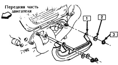
9.6. Front exhaust manifold heat shield parts: 1 - shield, 2 - washer, 3 - nut
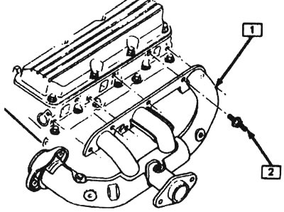
7. Loosen the exhaust manifold mounting bolts and disconnect the manifold from the cylinder head (see illustration).
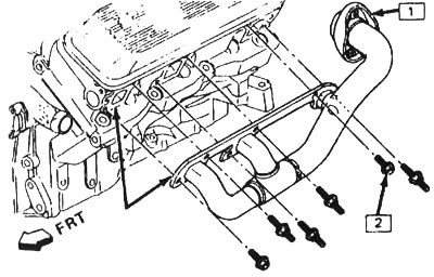
9.7. Front exhaust manifold mounting parts: 1 - manifold, 2 - bolt
Rear exhaust manifold
8. Disconnect the cable from the negative terminal of the battery.
9. Disconnect the wires from the spark plugs of the rear cylinders (see chapter 1, section 33).
10. Disconnect the throttle cable bracket.
11. Remove the bypass pipe heat shield.
12. Remove the two bolts securing the bypass pipe to the rear exhaust manifold.
13. Remove the plastic tank attached to the deflector.
14. Raise the vehicle and support it securely on stands.
15. Remove the manifold heat shield, if present (see illustration).
9.15. Rear exhaust manifold heat shield parts: 1 - shield, 2 - fastening parts
16. Remove the catalytic converter heat shield and its suspension.
17. Loosen the automatic transmission hydraulic fluid level dipstick tube bracket and remove the tube.
18. Disconnect the oxygen sensor connector.
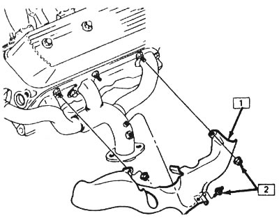
19. Remove the three nuts from the bottom of the exhaust manifold (see illustration).
9.19. Rear exhaust manifold parts: 1 - manifold, 2 - bolt
20. Lower the vehicle.
21. Remove the engine lift bracket.
22. Unscrew the three upper exhaust manifold mounting nuts and separate the manifold from the head.
23. If you want to replace the manifold itself, remove the oxygen sensor (see chapter 6, section 4) and install it on the new manifold.
Installation
24. Clean the mating surfaces of the exhaust manifold and cylinder head from any remaining old gasket material, then check the manifold for deformations and cracks. If the manifold gasket is torn, take the manifold to a repair shop to have its surface re-treated.
25. Install the manifold in place with a new gasket and tighten its mounting bolts by hand.
26. Starting from the centre and working towards the edges, tighten the mounting bolts one by one until they are all tightened to the required torque specified in the specifications given in this chapter.
27. Install the remaining parts in reverse order.
28. After starting the engine, check the joints between the manifold and the cylinder head and between the manifold and the exhaust pipe for exhaust gas leaks.