
Contents: Removal ↧ Installation ↧
Removal
1. Relieve the pressure in the fuel supply system (see chapter 4, section 2).
2. Disconnect the cable from the negative terminal of the battery.
3. Remove the air intake and throttle body (see chapter 4, sections 12, 13).
4. Remove the fuel distribution pipe and injectors (see chapter 4, section 13).
5. Remove the heat shield from the exhaust manifold bypass pipe (see section 9).
6. Disconnect the control cables from their brackets (see chapter 4, section 9).
7. Remove the power steering pump mount from the manifold (see chapter 10, section 19). Pay attention to the location of the fastening parts, this will be useful during assembly.
8. Loosen the generator clamp and turn it to the side. Separate the generator from its mounting bracket (see chapter 5, section 13). Pay attention to the location of the fastening parts for subsequent assembly.
9. Drain the coolant from the cooling system (see chapter 1, section 29).
10. Disconnect the heater tubes and hoses from the manifold.
11. Disconnect the bypass hose.
12. Tag and disconnect the fuel and vacuum hoses and all wiring harness connectors at the manifold. When disconnecting fuel hoses, wrap them with a rag to prevent any remaining fuel from leaking out. To prevent contamination from entering, plug the pipes with plugs.
13. Loosen the intake manifold mounting bolts and remove the manifold. Do not insert a lever between the manifold and heads as this may damage the soft aluminum sealing surfaces.
14. If you are installing a new manifold, transfer all mounting parts and sensors to it.
Installation
Note: The mating surfaces of the cylinder head, cylinder block and manifold must be perfectly clean before installing the manifold. There are solvents for removing gaskets; they are convenient for removing old gasket material stuck to the heads and manifold (since the manifold is made of aluminum, scraping may damage its surfaces). When using solvent, strictly follow the instructions printed on its packaging.
15. Use a scraper to remove any remaining sealing material and gaskets (see illustration), then clean the mating surfaces with varnish thinner or acetone. If, when installing the manifold, traces of sealant or grease remain on the mating surfaces, oil leakage or air suction may occur through these areas. Use a vacuum cleaner to remove any gasket material that may have fallen into the intake ports or tappet recesses.
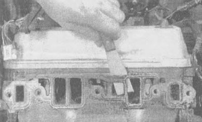
7.15 Remove all remaining gasket material, but be careful not to scratch the mating surfaces of the manifold and cylinder head
16. Run the threads in the bolt holes with a tap of the appropriate size, then use a jet of compressed air (if there is a source) remove chips from the holes.
Caution! When using compressed air, wear safety glasses or a face shield!
17. If steel manifold gaskets are used, apply a thin, even coat of sealant, such as K&W Copper Coat, to both sides of the gaskets before placing them on the cylinder heads (or its equivalent). Apply a bead of room temperature curing RTV sealant to the lips of the new manifold-to-block seals, then install the seals. Make sure the sharp end of the seal is tight against both the head and the block (see illustration).
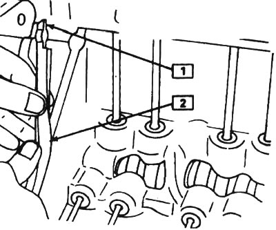
7.17. Installing manifold and block seals: 1 - area where sealant should be applied, 2 - seal
18. Carefully lower the manifold into place. Apply a layer of sealant to the threads of the mounting bolt and tighten the mounting bolts by hand.
19. Tighten the bolts in two stages, following the sequence shown in the illustration, until all of them are tightened to the required torque specified in the Tightening Torques subsection of this chapter.
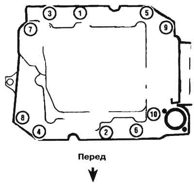
7.19. Intake Manifold Bolt Tightening Sequence
20. Install the remaining parts in reverse order.
21. Change the oil and oil filter (see chapter 1, section 12), fill the cooling system (see chapter 1, section 29). Start the engine and check the system for oil leaks or air intake.
The material was created based on information from the website ChevyMan