
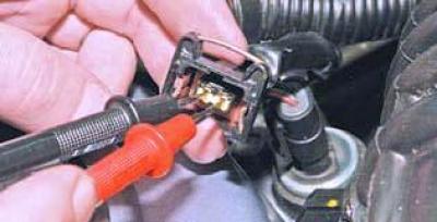
We connect the tester probes to terminals "1" and "2" of the wiring harness block.
When the ignition is on, the voltage should be 4.5–5.5 V.
Otherwise, we check the serviceability of the circuits (open circuit and short circuit to ground) between terminal "2" of the engine management system wiring harness connector and terminal "M7" of the ECU wiring harness connector, as well as between terminal "1" of the engine management system wiring harness connector and terminal "M64" of the ECU wiring harness connector.
If the circuits are in good condition and there is no voltage, the ECU is faulty.
To check the air temperature sensor…
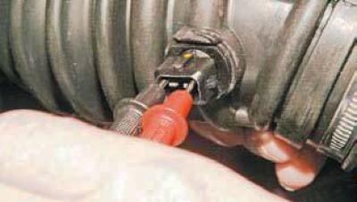
…we use a tester to measure the resistance between its terminals at different air temperature values in the air supply hose to the throttle assembly (warmed up and unwarmed up engine).
At the same time, we use a thermometer to measure the temperature of the surrounding air in the hose next to the sensor.
The obtained resistance values are compared with the control values (see table).
We replace the faulty air temperature sensor in the intake manifold with a new one along with the air supply hose to the throttle assembly.
Control values of resistance of the air temperature sensor in the intake manifold (approximately)
| Air temperature,°C | Resistance, Ohm |
| -10 | 16 000 |
| 0 | 9 400 |
| 10 | 5 700 |
| 20 | 3 500 |
| 40 | 1 500 |
The text of the article was obtained from the website ChevyMan