


…disconnect the engine management system wiring harness connector from the speed sensor.
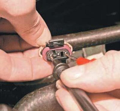
We connect the tester probes to terminals "A" and "C" of the wiring harness block.
When the ignition is on, the voltage should be equal to the voltage of the on-board network.
Similarly, we measure the voltage between terminals "A" and "B".
When the ignition is on and the on-board network voltage is 12.5–13.0 V, the device should record a voltage of 10.5–11.0 V.
If the voltage value does not correspond to the norm, we check the serviceability of the circuit (open circuit and short circuit to ground) between the terminal "B" of the engine control system wiring harness connector and the terminal "K6" of the ECU wiring harness connector.
We also check the integrity of fuse F14 (15A) of the mounting block located in the passenger compartment, and the serviceability of the circuit (open circuit and short circuit to ground) between terminal "C" of the engine control system harness connector and the mounting block.
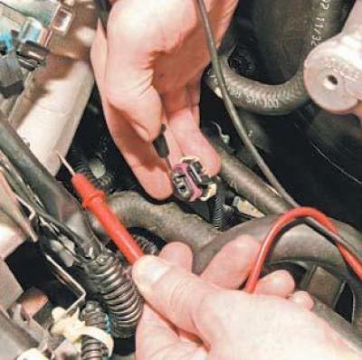
Having connected the tester probes to the terminal "A" of the block and the engine "ground", we measure the resistance of the "ground" circuit.
If the sensor ground circuit is in good condition, the device should record a resistance of less than 1 Ohm.
The reason for increased resistance may be an unreliable connection in the pads connected to the sensor or to the ECU.
If the sensor circuits are OK, the ECU is faulty.
To check the speed sensor, remove it (see Removal the vehicle speed sensor) and connect the wiring harness block to the sensor.
From the side where the wires enter the block, we insert a piece of wire into the socket corresponding to terminal "B" so that contact appears between it and the terminal.
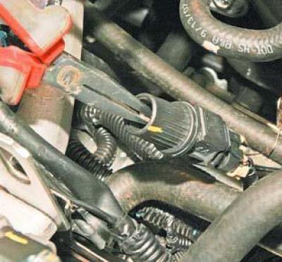
Slowly rotating the speed sensor sleeve, use a tester to measure the voltage between terminal "B" and "ground".
When the ignition is on, the device should record regularly alternating voltage values I (below 0.5 V) and II (above 10.0 V).
We replace the faulty speed sensor with a new one.