
With the ignition off, disconnect the engine management system wiring harness connector from the throttle position sensor (see Removal the throttle position sensor).
To check the sensor power supply circuit…
…we connect the tester probes to terminals "A" and "B" of the socket.
When the ignition is on, the device should record a voltage of 4.5–5.5 V.
If there is no voltage, check the circuit (open circuit and short circuit to ground) between terminal "M32" of the ECU harness connector and terminal "A" of the wiring harness connector (power "+"). Also check the circuit between terminal "M64" of the ECU harness connector and terminal "B" of the connector — sensor grounding.
We check the serviceability of the circuit between the "M6" terminal of the ECU harness connector and the "C" terminal of the wiring harness connector.
If the circuits are in good condition, but the voltage is not normal, the ECU is faulty.
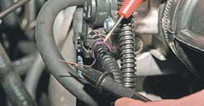
To check the sensor, connect the wiring harness block to it.
From the side where the wires enter the block, we insert two pieces of wire (or needles) into its sockets corresponding to terminals "A" and "C", so that contact appears between them and the terminals of the wires.

We connect the tester probes to the wire segments.
With the ignition on, measure the voltage between terminals "A" and "C". For a serviceable sensor, with the throttle valve closed, the voltage should be 3.9–4.9 V, and with the valve open, 0.1–0.9 V.
If the sensor output voltage is outside the specified ranges, the sensor must be replaced.
(The article was borrowed from the website ChevyMan.ru)