
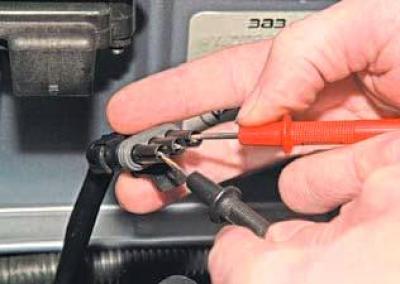
We connect the tester probes to terminals "A" and "C" of the wiring harness block.
When the ignition is on, the voltage should be 4.5–5.5 V.
Similarly, we measure the voltage between terminals "B" and "C".
The device should record a voltage of 4.5–5.5 V.
If the voltage values are not within the norm, we check the serviceability of the circuits (open circuit and short circuit to ground) between terminal "A" of the wiring harness connector and terminal "M48" of the ECU wiring harness connector, between terminal "B" of the wiring harness connector and terminal "M8" of the ECU wiring harness connector, and also between terminal "C" of the wiring harness connector and terminal "M16" of the ECU wiring harness connector.
If the voltage values do not match the serviceable circuits, the ECU is faulty.
To check the sensor, connect the wiring harness block to it.
From the side of the wire input into the socket of the block corresponding to the terminal "B", we insert a piece of wire so that contact appears between it and the terminal.
With the ignition on and creating a vacuum (through the vacuum supply hose to the sensor)…
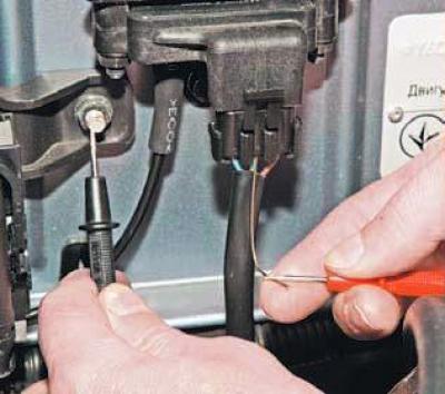
..we measure the voltage between terminal "B" of the wiring harness connector and "ground".
The device readings should change from 4.5 to 5.5 V (atmospheric pressure) up to 0.5–1.0 V (vacuum 68 kPa).
You can roughly estimate the sensor's performance by creating a vacuum in the hose with your mouth.
In this case, the voltmeter readings change from 4.5 V to 2.0 V.
We replace the faulty sensor with a new one.
(Original version of the article on the website: «chevyman.ru»)