


By visual inspection, make sure that the pressure regulator and its drive parts are not damaged, there is no leakage of brake fluid, plug 24 (see figure 6-22) recessed into the housing hole by 1-2 mm, there is no play in the connection of the rod 5 (see figure 6-5) with elastic lever 6 and regulator drive lever axis 9.
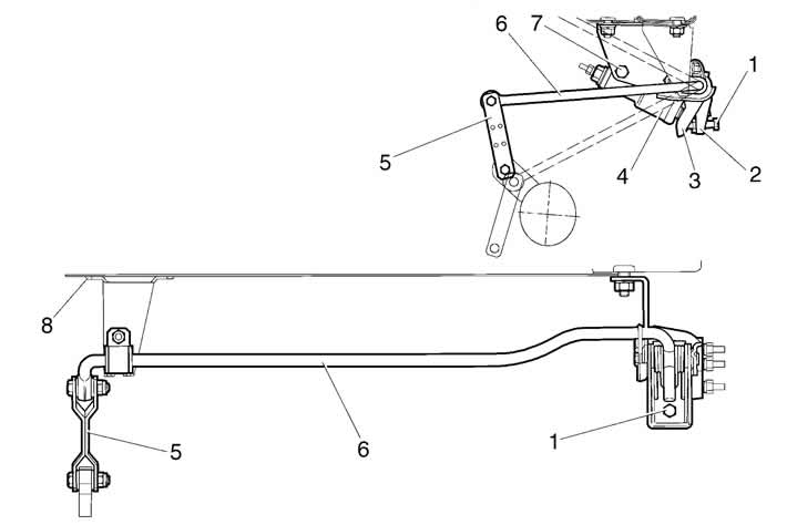
Figure 6-5. Rear brake pressure regulator installation diagram and adjustment:
1 - adjusting bolt;
2 - pressure regulator drive lever;
3 - pressure regulator drive piston lever;
4 - pressure regulator;
5 - traction;
6 - pressure regulator lever;
7 - regulator mounting bolt;
8 - support sleeve bracket.
Ask an assistant to press the brake pedal. Piston 2 (see figure 6-22) in this case it should extend from the housing by 1.6-2.4 mm, compressing spring 5 (see figure 6-6).
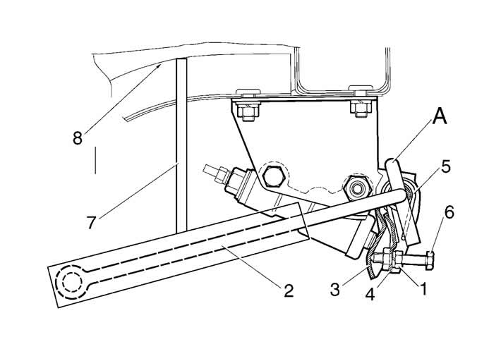
Figure 6-6. Installing the rear brake pressure regulator drive adjustment tool:
1 - lock nut;
2 - pressure regulator drive lever;
3 - pressure regulator drive piston lever;
4 - pressure regulator drive lever;
5 - spring;
6 - adjusting bolt;
7 - fixture rod;
8 - body bottom;
h = 200+5 mm - distance between the bottom and the lever.
Failure to comply with the listed requirements, lack of piston stroke, as well as its insufficient or excessive stroke indicate a malfunction of the regulator or its drive. In this case, repair or replace the pressure regulator, and after its installation, adjust its drive.