
Brake system of the car Chevrolet Niva 1

The structure of the braking system
The diagram of the brake system is shown in Figure 6-1. Figure 6-1. Brake system diagram: 1 - rear brake wheel cylinder; 2 - rear parking brake cable; 3 - rear...
The diagram of the brake system is shown in Figure 6-1. Figure 6-1. Brake system diagram: 1 - rear brake wheel cylinder; 2 - rear parking brake cable; 3 - rear...

Checking pipelines and connections
To prevent sudden failure of the brake system, carefully check the condition of all pipes: metal pipelines should not have dents, cracks and should be located...
To prevent sudden failure of the brake system, carefully check the condition of all pipes: metal pipelines should not have dents, cracks and should be located...

Checking the performance of the vacuum booster
Press the brake pedal 5-6 times with the engine off to create air in the cavities (figure 6-2) the same pressure, close to atmospheric. At the same time, by...
Press the brake pedal 5-6 times with the engine off to create air in the cavities (figure 6-2) the same pressure, close to atmospheric. At the same time, by...

Adjusting the position of the brake light switch
The adjustment is carried out by moving the switch 7 (figure 6-3) brake light with nut 6 released. Install the switch so that its buffer is located relative to...
The adjustment is carried out by moving the switch 7 (figure 6-3) brake light with nut 6 released. Install the switch so that its buffer is located relative to...

Adjusting the parking brake
If the parking brake does not hold the vehicle on a slope of up to 24% when the lever is moved to 7-14 notches of the sector, adjust it in the following order:...
If the parking brake does not hold the vehicle on a slope of up to 24% when the lever is moved to 7-14 notches of the sector, adjust it in the following order:...

Checking the performance of the pressure regulator
Place the car on a lift. By visual inspection, make sure that the pressure regulator and its drive parts are not damaged, there is no leakage of brake fluid,...
Place the car on a lift. By visual inspection, make sure that the pressure regulator and its drive parts are not damaged, there is no leakage of brake fluid,...

Adjusting the pressure regulator drive
Disconnect lever 2 (figure 6-6) from thrust 5 (figure 6-5) and attach the pressure regulator drive adjustment device to its end. Direct the rod 7 (figure 6-6)...
Disconnect lever 2 (figure 6-6) from thrust 5 (figure 6-5) and attach the pressure regulator drive adjustment device to its end. Direct the rod 7 (figure 6-6)...

Removal air from the hydraulic drive
Air that gets into the brake hydraulic system when replacing pipes, hoses, sealing rings, or when the system is leaking causes an increase in the free travel...
Air that gets into the brake hydraulic system when replacing pipes, hoses, sealing rings, or when the system is leaking causes an increase in the free travel...

Clutch and brake pedal bracket
Removal and installation. To remove the pedal bracket: remove the steering shaft bracket as described in the section " Steering "; disconnect the vacuum...
Removal and installation. To remove the pedal bracket: remove the steering shaft bracket as described in the section " Steering "; disconnect the vacuum...
Vacuum brake booster
Removal and installation. When removing the vacuum booster, the master cylinder of the brake hydraulic drive is not disconnected from the hydraulic system, so...
Removal and installation. When removing the vacuum booster, the master cylinder of the brake hydraulic drive is not disconnected from the hydraulic system, so...

Brake master cylinder
Master cylinder (figure 6-9) with a sequential arrangement of pistons. A tank is attached to the body of the main cylinder, in the filler neck of which a brake...
Master cylinder (figure 6-9) with a sequential arrangement of pistons. A tank is attached to the body of the main cylinder, in the filler neck of which a brake...

Front brake device
The front brake device is shown in Figure 6-11. Figure 6-11. Front wheel brake mechanism: 1 - cylinder block; 2 - brake pads; 3 - caliper clamping lever; 4 -...
The front brake device is shown in Figure 6-11. Figure 6-11. Front wheel brake mechanism: 1 - cylinder block; 2 - brake pads; 3 - caliper clamping lever; 4 -...

Removal and installation the front brake
Removal: Raise the front of the car, place it on stands and remove the wheel. Remove the hose guide brackets. Unscrew the bypass bolts, disconnect hose 10 from...
Removal: Raise the front of the car, place it on stands and remove the wheel. Remove the hose guide brackets. Unscrew the bypass bolts, disconnect hose 10 from...

Disassembling and assembling the front brake
Remove the cotter pins, then the axles 4 (see figure 6-11), holding the pressure levers 3 so that the springs do not jump out. Remove the pressure levers and...
Remove the cotter pins, then the axles 4 (see figure 6-11), holding the pressure levers 3 so that the springs do not jump out. Remove the pressure levers and...

Checking the thickness of the front brake disc
To assess the wear of the discs, it is necessary to remove the front wheels. The thickness of the discs should be checked with a micrometer by measuring the...
To assess the wear of the discs, it is necessary to remove the front wheels. The thickness of the discs should be checked with a micrometer by measuring the...

Checking the runout of the front brake disc
Check the axial runout of the brake disc without removing it from the vehicle (figure 6-15). The maximum permissible runout on the indicator is 0.15 mm; if the...
Check the axial runout of the brake disc without removing it from the vehicle (figure 6-15). The maximum permissible runout on the indicator is 0.15 mm; if the...

Replacing the front brake pads
A preliminary assessment of the wear of the linings is carried out with the front wheels removed through the window in the caliper 6 (see figure 6-11). If the...
A preliminary assessment of the wear of the linings is carried out with the front wheels removed through the window in the caliper 6 (see figure 6-11). If the...

Rear brake device
The rear brake device is shown in Figure 6-18. Figure 6-18. Rear wheel brake mechanism: 1 - wheel cylinder; 2 - upper brake shoe tension spring; 3 - pad pad; 4...
The rear brake device is shown in Figure 6-18. Figure 6-18. Rear wheel brake mechanism: 1 - wheel cylinder; 2 - upper brake shoe tension spring; 3 - pad pad; 4...
Removal and disassembling the rear brake
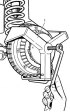
Raise the rear of the car and remove the wheel. With a puller (figure 6-19) remove the brake drum. Disconnect from the lever 18 (see figure 6-18) manual brake...
Raise the rear of the car and remove the wheel. With a puller (figure 6-19) remove the brake drum. Disconnect from the lever 18 (see figure 6-18) manual brake...

Assembly and installation of the rear brake
Assembly and installation should be carried out as follows. Install and secure the wheel cylinder to the brake shield, connect the pipeline to it and tighten...
Assembly and installation should be carried out as follows. Install and secure the wheel cylinder to the brake shield, connect the pipeline to it and tighten...

Disassembly and assembly of rear brake wheel cylinders
Disassemble and assemble wheel cylinders as follows. Remove protective caps 2 (figure 6-20), then press out pistons 4 from cylinder body 3 together with the...
Disassemble and assemble wheel cylinders as follows. Remove protective caps 2 (figure 6-20), then press out pistons 4 from cylinder body 3 together with the...

Checking the rear brake components
Wheel cylinders. Check the cleanliness of the working surfaces of the cylinder, pistons and thrust rings. The surfaces must be completely smooth, without...
Wheel cylinders. Check the cleanliness of the working surfaces of the cylinder, pistons and thrust rings. The surfaces must be completely smooth, without...

Checking the rear brake wheel cylinders on the stand
Install cylinder 2 (figure 6-23) on the stand, connect the pipeline from the pressure gauges to it and pump the system. Figure 6-23. Rear brake wheel cylinder...
Install cylinder 2 (figure 6-23) on the stand, connect the pipeline from the pressure gauges to it and pump the system. Figure 6-23. Rear brake wheel cylinder...

Rear brake pressure regulator
Removal and installation. Disconnect the lever 23 (figure 6-24) from rod 16, and then clip 18 from the body bracket. Figure 6-24. Pressure regulator drive...
Removal and installation. Disconnect the lever 23 (figure 6-24) from rod 16, and then clip 18 from the body bracket. Figure 6-24. Pressure regulator drive...

Parking brake
Removal and installation. Set the parking brake drive lever to the lowest position, disconnect the ends of the cables from the brake shoe drive levers (see "...
Removal and installation. Set the parking brake drive lever to the lowest position, disconnect the ends of the cables from the brake shoe drive levers (see "...
This section is available at russian, bulgarian, belarusian, ukrainian, serbian, croatian, romanian, polish, slovak, hungarian
See similar sections on Chevrolet cars:
Chassis: Brake system Chevrolet Aveo T300 (2012-2018)
Chassis: Brake system Chevrolet Captiva 1 (2006-2018)
Chassis: Brake system Chevrolet Cruze 1 (2008-2016)
Chassis: Brake system Chevrolet Lacetti 1 (2002-2009)
Chassis: Brake system Chevrolet Lanos T150 (2002-2009)
Chassis: Brake system Chevrolet Tahoe 1 (1992-2000)
Chassis: Brake system Chevrolet Lumina 1 (1989-1994)
Share information:
- General information
- Vehicle device
- User manual
- Maintenance
- Power unit
- Engine repair
- Cooling system
- Lubrication system
- Power and exhaust system
- Transmission
- Clutch
- Car gearbox
- Transfer case
- Cardan gear
- Rear axle
- Front axle
- Chassis
- Suspension and shock absorbers
- Steering
- Brake system
- Body
- Exterior (external elements)
- Interior (internal elements)
- Ventilation and heating
- Electrical equipment
- Power devices
- Lighting and appliances