


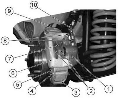
Figure 6-11. Front wheel brake mechanism:
1 - cylinder block;
2 - brake pads;
3 - caliper clamping lever;
4 - axis of the clamping lever;
5 - shoe guide;
6 - brake caliper;
7 - brake disc;
8 - air bleed nipples;
9 - protective cover;
10 - brake hose.
Remove cylinder block 1 from the caliper grooves by spreading the caliper grooves to 118.5 mm and pressing on retainer 12 (figure 6-13). Remove the dust caps 3 from the cylinders.
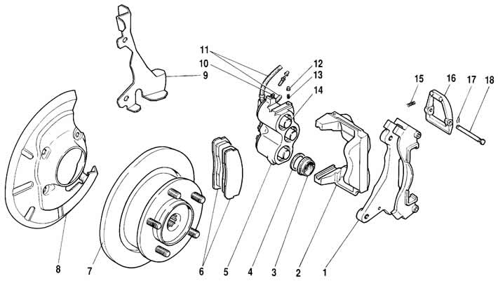
Figure 6-13. Front brake parts:
1 - shoe guide;
2 - brake caliper;
3 - piston protective cap;
4 - sealing ring;
5 - cylinder block;
6 - brake pads;
7 - brake disc;
8 - caliper protective cover;
10 - air bleed nipple;
11 - brake hoses;
12 - cylinder block retainer;
13 - retainer spring;
14 - piston;
15 - spring of the pressure lever;
16 - pressure lever;
17 - cotter pin;
18 - axis of the pressure lever.
By forcing a stream of compressed air through the brake fluid inlet, push pistons 14 out of the cylinder block and remove sealing rings 4.
Assemble the front brake in the reverse order of disassembly. Lubricate the sealing rings, pistons and cylinder mirrors with brake fluid during assembly, and put DT-1 grease under the protective caps.
[The original source of the article is the website CHEVYMAN.ru]