


Contents: Disassembly procedure ↧ Assembly procedure ↧
Disassembly procedure
1. Remove the starter. Follow step "Starter" in this section.
2. Remove the starter through-bolts.
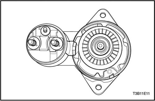
3. Remove the commutator end piece and brush holder.
4. Check the brushes, protruding springs and brush holders for wear or damage. Replace the unit if necessary.
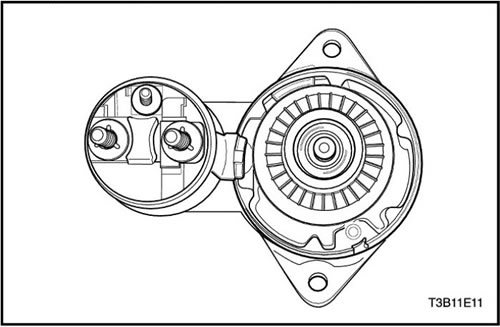
5. Check the armature for free play. If the armature does not rotate freely, disassemble the assembly starting with step 14. Otherwise, perform a no-load armature test.
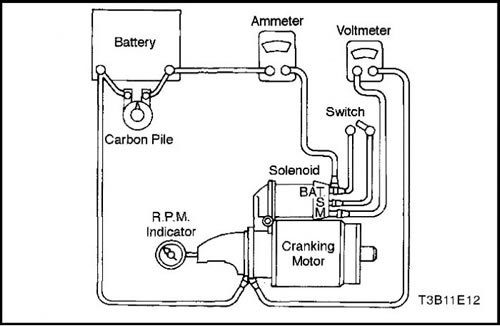
Note: Perform the test in the shortest possible time to avoid overheating and damaging the electromagnetic relay.
Important: If the rated current consumption does not include the electromagnetic relay, subtract the rated current consumption from the value of the self-locking winding.
6. To start the no-load test, close the switch and compare the RPM and voltage with the specifications. Follow step "Starter Specifications" in this section. Disconnect only when the switch is open. Use the test results as follows:
- If the current consumption and no-load speed correspond to the nominal values, then the starter is normal.
- Low speed with high current consumption indicates increased friction caused by overtightened, dirty or worn bearings, a bent armature shaft, a short circuit on the armature shaft or on the excitation coils.
- The immobility of the starter with high current consumption can be caused by a short circuit to ground of the terminals or windings or "seized" bearings.
- The starter not moving when there is no current consumption may be caused by a break in the circuit in the armature windings, broken or worn brush springs, high resistance between the collector lamellas or other reasons that prevent good contact between the brushes and the collector.
- Low no-load speed and low current indicate high internal resistance and high current consumption, which are usually caused by shorted excitation coils.
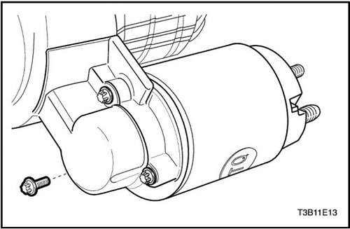
7. Remove the electromagnetic relay screws.
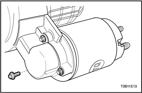
8. Remove the excitation coil connector nut. Disconnect the excitation coil connector.
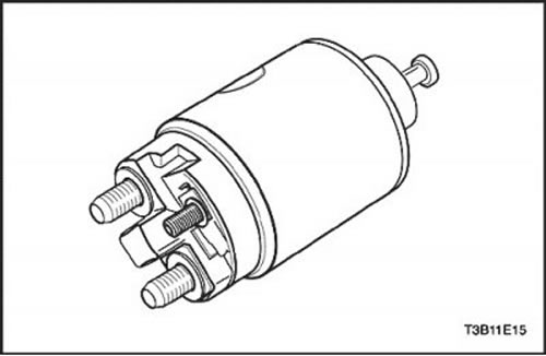
9. Remove the return spring.
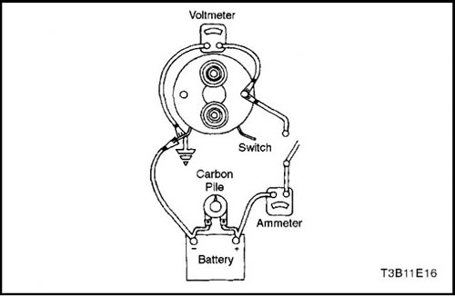
Important: If the solenoid is not removed from the starter, the connectors from the solenoid terminals must be removed before performing this test.
10. Check the electromagnetic relay coils by measuring the current consumption.
- Check the self-locking windings by connecting an ammeter in series to the 12-volt battery, switch and ground.
- Connect the carbon film resistor to the battery.
- Adjust the voltage to 10 V. The ammeter reading should be between 13 and 19 A. The current will drop as the windings heat up. Current consumption below the specifications indicates a short circuit or a short to ground in the winding. Both require replacing the electromagnetic relay. Current consumption above the specifications indicates increased resistance. No current indicates a broken circuit.
Important: The current will drop when the windings heat up. Current consumption below the technical specifications indicates a short circuit or a short to ground of the winding. Both require replacement of the electromagnetic relay. Current consumption above the technical specifications indicates increased resistance. No current indicates a break in the circuit.
11. Check both windings by connecting them as per the previous check.
- Connect the electromagnetic relay terminal to ground.
- Adjust the voltage to 10 V. The ammeter reading should be between 59 and 79 A.
- Check connections and replace solenoid relay if necessary.
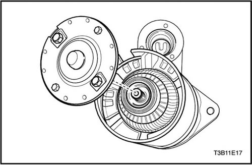
12. Remove the stator with the armature from the starter assembly.
13. Remove the cover.
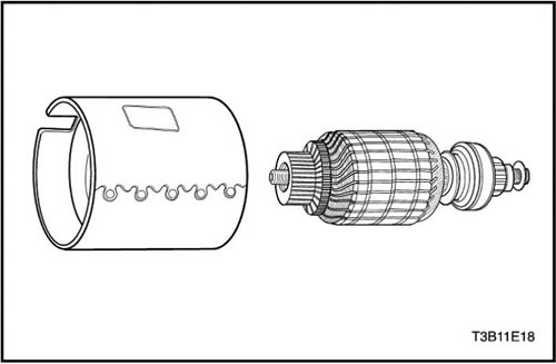
14. Remove the stator from the anchor.
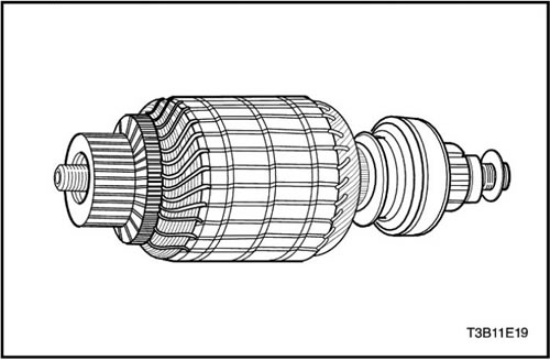
15. Check the shaft and gears for discoloration, breakage or wear. Replace if necessary.
16. Check the anchor commutator. If the commutator is rough, it needs to be ground down. The outer diameter of the commutator should be no less than 26.9-27.1 mm (1.059-1.067 inches) after turning or cutting. Do not turn eccentric collectors.
17. Check the places where the anchor wires touch the commutator fins. Make sure there is good contact. Burnt commutator fins indicate poor contact.
18. If testing equipment is available, check the armature for short circuits by mounting it on the tester and holding the saw blade on the armature core and rotating the armature. If the saw blade vibrates, replace the armature.
19. Check the anchor after cleaning the anchor lamellas. If the saw blade vibrates, replace the anchor.
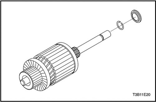
20. Remove the snap ring from the groove in the drive shaft.
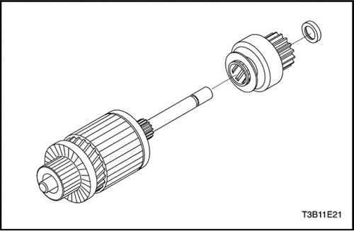
21. Remove the thrust ring and gear from the shaft.
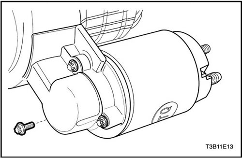
22. If not done in the previous steps, remove the screws securing the electromagnetic relay to the housing and remove the nut from the excitation coil connector.
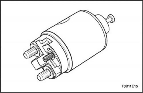
23. Turn the relay 90 degrees and remove it together with the return spring.
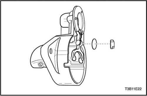
24. Remove the piston with protective cover and the starting lever. Check the electromagnetic relay windings if this was not done in step 11.
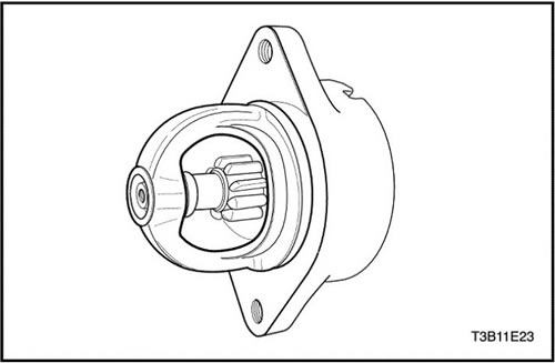
Important: The gear clearance must be normal so that the protrusions on the starting lever clamp do not hit the connecting flange during starting.
25. After disassembling the starter and replacing the electromagnetic relay, it is necessary to check the gear clearance.
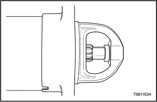
26. Disconnect the excitation coil connector from the electromagnetic relay terminal and carefully insulate the connector.
27. Connect one 12-volt wire to the solenoid terminal and the other to the starter housing.
28. Using a shorting wire, establish a short contact between the solenoid valve connector and the starter housing so that the pinion moves to the start position and remains there until the battery is disconnected.
Important: There is no means for adjusting the gear clearance on the starter. If the clearance is outside the established limits, check the correct installation and replace worn parts.
29. Move the pinion as far back as possible to accommodate any movement and check the clearance with a feeler gauge. The clearance should be between 0.25 and 3.56 mm (from 0.01 to 0.14 inches).
Assembly procedure
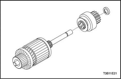
1. Install the thrust ring and gear onto the shaft.
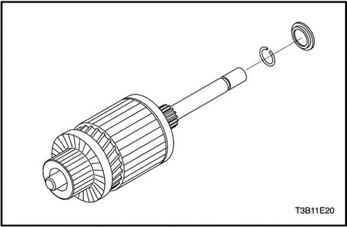
2. Place the retaining ring on the shaft groove and insert the flange.
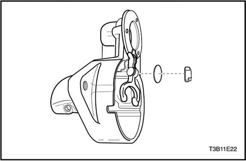
3. Install the trigger lever, washer and elastic gasket.
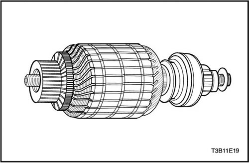
4. Lubricate the drive end of the armature shaft.
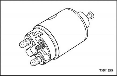
5. Install the electromagnetic relay assembly.
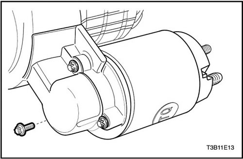
6. Tighten the electromagnetic relay with screws.
Tighten
Tighten the solenoid relay screws to 8 Nm (71 lbs/ft).
7. Install the excitation coil connector to the starter terminal. Install the nut.
Tighten
Tighten the starter excitation coil connector nut to 8 N·m (71 lbs.in).
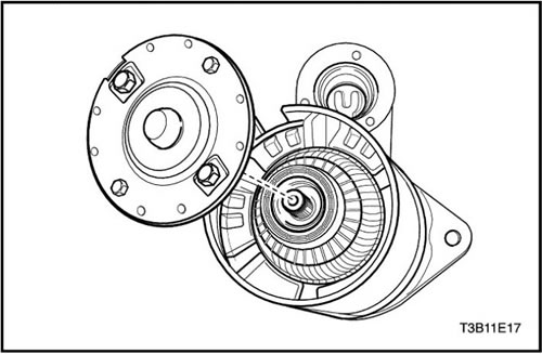
8. Install the anchor in the stator.
9. Install the cover on the anchor and stator.
10. Install the anchor and stator with the cover into the starter housing.
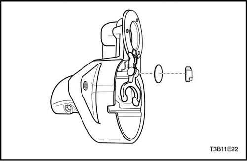
11. Install the end piece of the collector and the brush holder, aligning its holes with the through holes in the housing.
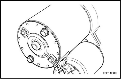
12. Install the starter through-bolts.
13. Install the starter. Follow the step "Starter" in this section.
Tighten
Tighten the starter through bolts to 6 N·m (53 lbs.in).
(The source of the article is available on the website «CHEVYMAN.RU»)