
ChevyMan.ru
Mazda Mitsubishi Toyota Land Rover Honda Kia Nissan
English Русский
Български
Беларускі
Український
Српски
Hrvatski
Română
Polski
Slovenský
Magyar
|
Articles | Sitemap | Contacts |


Home   Aveo   Captiva   Cruze   Lacetti   Lanos   Niva   Tahoe   Others  
Cruze 1 (2008-2016)
  • Home
  • Cruze
  • J300 (2008-2016)
  • Power unit
  • Engine repair
  • Disassembling the engine

Disassembling the engine (Chevrolet Cruze J300)

            0

You will need: 13 mm and 17 mm wrenches, tools needed to remove the cylinder head, screwdrivers, a hammer, an oil filter remover, a piston pin press tool or a suitable mandrel, and pliers.

Helpful Hint: If possible, work on a special rotating stand that provides access to the engine from all sides, as it is very difficult to secure the engine from moving when loosening fastening parts that are tightened with a high torque.


1. Remove the engine from the vehicle (see "Removal and installation the engine").

2. Remove the starter (see "Removal and installation the starter").

3. Remove the generator (see "Removal and installation the generator").

4. Disconnect the gearbox from the engine by unscrewing the bolts that secure it to the engine (see "Removal and installation of a manual gearbox").

5. Remove the clutch from the flywheel (see "Removal and installation the clutch").

6. Remove the flywheel (see "Removal, defect detection and installation of the flywheel").

7. Remove the timing belt (see "Replacing the timing belt and its tension roller") and the rear cover of the drive (see "Removal and installation the oil pump").

8. Remove the cylinder head (Ohm. "Replacing the cylinder head gasket").
8. Remove the cylinder head (Ohm. «Replacing the cylinder head gasket»).


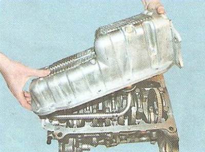
9. Remove the oil pan (see "Replacing the oil pan seal"),


9. Remove the oil pan (see «Replacing the oil pan seal»),


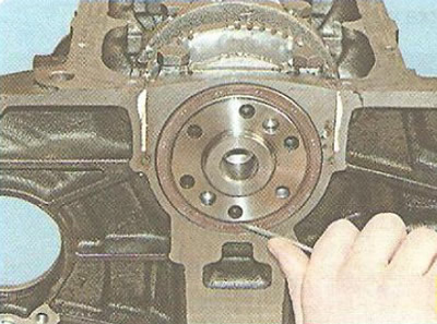
10. Using a screwdriver, remove the rear crankshaft oil seal from the cylinder block socket.
10. Using a screwdriver, remove the rear crankshaft oil seal from the cylinder block socket.


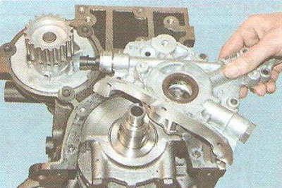
11. Remove the oil receiver, oil pump and the gasket installed underneath it (see "Removal and installation the oil pump").
11. Remove the oil receiver, oil pump and the gasket installed underneath it (see «Removal and…


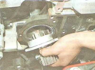
12. ...and also a water pump (see "Replacing the water pump").

13. Remove the oil filter (see "Changing engine oil and oil filter").


Helpful Hint: When disassembling the crank mechanism and piston group, mark the pistons, connecting rods, main and connecting rod bearing shells so that when reassembling, you can install them in their original places if they are in working order.

Helpful Hint: When disassembling the crank mechanism and piston group, mark the pistons, connecting…


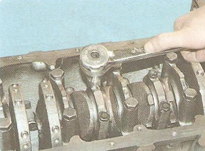
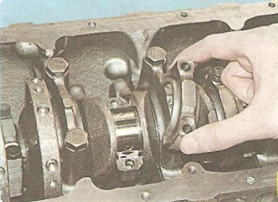
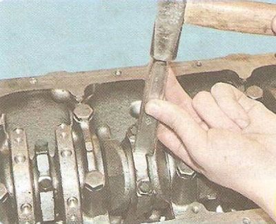
14. Unscrew the two bolts securing the connecting rod cover of any cylinder, move the connecting rod cover from its seat using light hammer blows through a wooden spacer...
14. Unscrew the two bolts securing the connecting rod cover of any cylinder, move the connecting…


15. ...and remove the cover with the insert.
15. ...and remove the cover with the insert.


Warning: The cover and connecting rod are marked with symbols (triangle icon and number). When assembling the engine, the number and the symbol should be located on the same side. However, the connecting rod and cover are not marked with cylinder numbers. Be sure to mark them in any way possible (for example, by kerning), so that they can be installed in their original places during assembly, since the connecting rod caps are not interchangeable (the connecting rod is machined together with the cover).


Warning: The cover and connecting rod are marked with symbols (triangle icon and number). When…


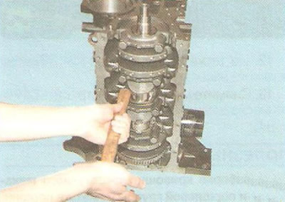
16. Press with a wooden block (with a hammer handle) on the connecting rod...
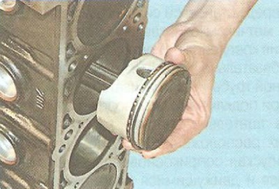
16. Press with a wooden block (with a hammer handle) on the connecting rod...


17. ...and remove the piston with the connecting rod from the cylinder towards the upper plane of the cylinder block.

18. Similarly, remove the pistons and connecting rods of the remaining cylinders, turning the crankshaft to access the connecting rod cap bolts.

Helpful Hint: Turn the crankshaft using a wrench on the chamfer at its front end.
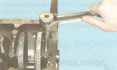

Helpful Hint: Turn the crankshaft using a wrench on the chamfer at its front end.


19. Remove the two bolts securing any main bearing cap. Separate the cap from its seat with light hammer blows through a wooden spacer...
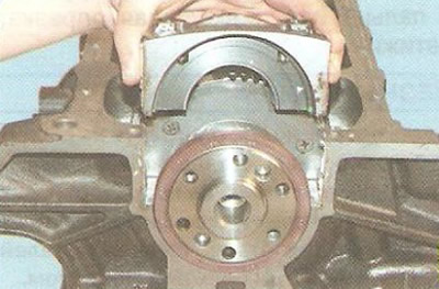


19. Remove the two bolts securing any main bearing cap. Separate the cap from its seat with light…


20. ...and remove the cover with the lower insert.
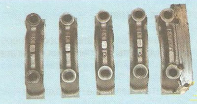
20. ...and remove the cover with the lower insert.


Warning: Main bearing caps are designed for one specific cylinder block only (the covers are processed together with the block). The covers are not interchangeable. The covers are numbered according to the order in which they are installed, counting from the front of the engine (there is no number on the cover of the fifth main bearing). The letters "VK" cast on the covers must be directed towards the left side of the engine during installation.
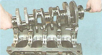

Warning: Main bearing caps are designed for one specific cylinder block only (the covers are…


21. Unscrew the bolts, remove the remaining main bearing caps and remove the crankshaft.
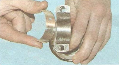


21. Unscrew the bolts, remove the remaining main bearing caps and remove the crankshaft.


22. Remove the bearing shells from all connecting rods...
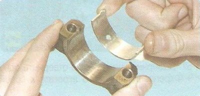
22. Remove the bearing shells from all connecting rods...


23. ...and from their lids...
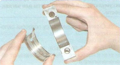
23. ...and from their lids...


24. ...from the main bearing caps...
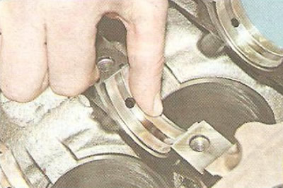
24. ...from the main bearing caps...


25. ...and from all beds in the cylinder block.
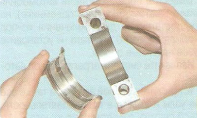
25. ...and from all beds in the cylinder block.


Note: The increased thickness of the third main bearing cap liner has flanges on the side ends that act as thrust half rings limiting the axial movement of the crankshaft.
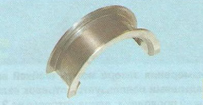

Note: The increased thickness of the third main bearing cap liner has flanges on the side ends that…


Similar flanges are made on the upper shell of the third main bearing.
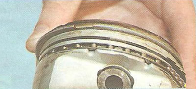
Similar flanges are made on the upper shell of the third main bearing.


26. Release the upper compression ring...
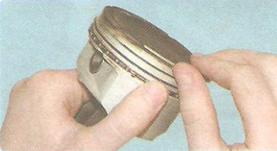
26. Release the upper compression ring...


27. ...and take it off.
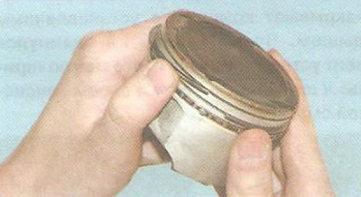
27. ...and take it off.


28. Remove the lower compression ring in the same way.
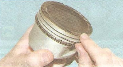
28. Remove the lower compression ring in the same way.


29. Unclamp and remove the top ring...
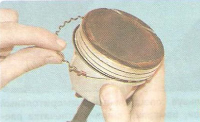
29. Unclamp and remove the top ring...


30. ...expander...
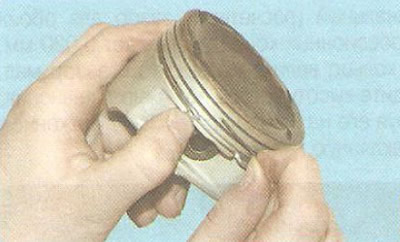
30. ...expander...


31. ...and the lower ring of the composite oil scraper ring.
31. ...and the lower ring of the composite oil scraper ring.


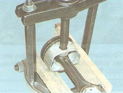
32. Press the pin out of the piston bosses and the upper head of the connecting rod.

Note: Do not heat the connecting rod before pressing out the pin. To avoid damaging the piston, use wooden shims when pressing out the pin, as shown in the photo.


Helpful Hint: Mark the parts. If they are not damaged and show little wear, they can be used in their original locations.


(The original article is on the website «ChevyMan»)

The article was checked: Vladimir Romannikov
This article is available at russian, bulgarian, belarusian, ukrainian, serbian, croatian, romanian, polish, slovak, hungarian

Share information:

Previous articles
Cruze 1: Engine repair
Next articles

Removal and installation the engine
Lapping valves
Disassembly, repair and assembly of the cylinder head
Replacing hydraulic compensators
Removal, inspection and installation of camshafts
Engine parts defect detection
Engine assembly
Design Features of F18D Engines
Checking and replacing the auxiliary drive belt of the F18D engine
Replacing and adjusting the timing belt of the F18D engine


See similar articles on the topic of Chevrolet cars:
The engine will not start Chevrolet Aveo T300 (2012-2018)
Engine coolant temperature gauge Chevrolet Captiva 1 (2006-2018)
Starting the engine from another car's battery («jump-starting») Chevrolet Lacetti 1 (2002-2009)
Starting the engine from another car's battery (jump-starting) Chevrolet Lanos T150 (2002-2009)
Disassembling the engine Chevrolet Niva 1 (2002-2016)
Disassembling the engine Chevrolet Tahoe 2 and 3 (2000-2014)
Engine bay and underbody of the car Chevrolet Lumina 1 (1989-1994)
Link in different formats to this page


Visitor comments

No comments yet


How much will 36 + 48 =


Cruze 1 (2008-2016) 
  • General information
  • User manual
  • Troubleshooting
  • Maintenance
  • Power unit
  • Engine repair
  • Lubrication system
  • Cooling system
  • Exhaust system
  • Supply system
  • Control system
  • Transmission
  • Clutch
  • Car gearbox
  • Front wheel drives
  • Chassis
  • Front suspension
  • Rear suspension
  • Steering
  • Brake system
  • Body
  • Exterior (external elements)
  • Interior (internal elements)
  • Doors, covers and windows
  • Heating and air conditioning
  • Security systems
  • Electrical equipment
  • Equipment and devices
  • Power devices
  • Lighting and signaling
  • Electrical circuits


ChevyMan.ru © 2017-2026 · Mobile version · Feedback · Site search · Interesting to read · Sitemap: EN BG BY UA RS HR RO PL SK HU

Aveo 2003-2008 · Aveo 2006-2011 · Aveo 2012-2018 · Captiva 2006-2018 · Cruze 2008-2016 · Lacetti 2002-2009 · Lanos 2002-2009 · Niva 2002-2016 · Tahoe 1992-2000 · Tahoe 2000-2014 · Lumina 1 1989-1994 · Trailblazer 1 2001-2008 · Orlando 1 2010-2018 ·
🛡️ For your security and to improve our service, this site uses cookies. You can disable them in your browser.