


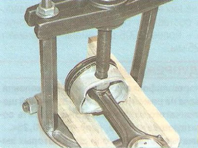
1. Insert the connecting rod into the piston, lubricate the piston pin with engine oil and press it into the connecting rod using the same device that was used to press out the pin, or using a hammer and a suitable mandrel inserted into the inner hole of the pin. The piston should be pressed with its boss against the upper head of the connecting rod in the direction of pressing the pin, which will allow it to take the correct position.
Note: The pin is inserted into the upper head of the connecting rod with tension, therefore, to facilitate assembly and maintain its fit, it is recommended to heat the connecting rods by placing them with the upper heads in an electric furnace heated to 240°C for 15 minutes. The heating temperature of the connecting rod can be controlled using a thermochromic pencil. To properly connect the pin to the connecting rod, press the pin as quickly as possible, since after it cools down, the position of the pin can no longer be changed.
2. Install the piston rings in the reverse order of removal, arranging them as shown in Fig. 5.12.
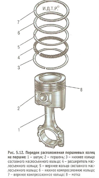
Warning: When installing, do not spread the rings more than necessary to avoid deformation or breakage.
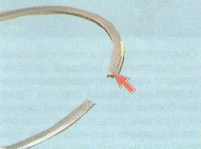
Note: Install the lower compression ring with the notch facing down (shown by arrow) into the second groove.
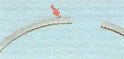
The "Y" marking on the compression rings must face upward.
3. Orient the rings as shown in Fig. 5.13. Install the rings on the remaining pistons.
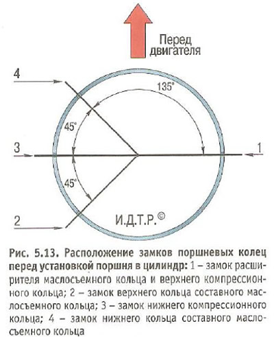
Note: The locks of the upper and lower rings of the composite oil scraper ring must be located at a distance of 25-30 mm, respectively, to the left and right of the expander lock.
4. Place the upper main bearing shells in the cylinder block bed.
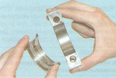
Note: Place a thicker liner with support flanges into the bed of the middle (third) main bearing.
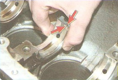
Install the inserts so that the insert's mounting tab aligns with the recess in the bed.
5. Lubricate the bearings with engine oil.
6. Install the crankshaft into the cylinder block.
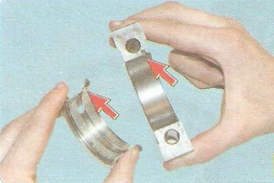
7. Place the lower bearing shells into the main bearing caps, aligning the tabs on the shells with the recesses on the caps.
Note: The upper and lower main bearing shells may differ in the location of the oil supply hole. Install the shells so that these holes coincide with the holes in the oil supply channels in the main bearing support beds. After installing the shells in the sockets, their ends protrude slightly outward, therefore, to correctly orient the shells when finally tightening the bearing cap mounting bolts, make sure that the protrusion of both ends is the same.
8. Lubricate the crankshaft main journals with engine oil.
9. Lubricate the liners in the crankshaft main bearing caps with engine oil.
10. Install the main bearing caps according to the serial numbers, aligning them with the marks.
Warning: Use a soft-faced hammer made of brass, lead or polyurethane to install the crankshaft bearing caps. Do not install the caps by tightening the fasteners, as this will damage the seating surfaces of the caps and the cylinder block.
11. Install the cover bolts, tighten the bolts evenly until they stop, without tightening them completely, unscrew them one turn, tighten them to a torque of 50 N·m (5.0 kgf·m) and turn them another 50°, and then another 15°.
Warning: Be sure to replace the main bearing cap bolts with new ones.
12. Check the correct assembly by turning the crankshaft by hand a few revolutions. The shaft should rotate freely and smoothly.
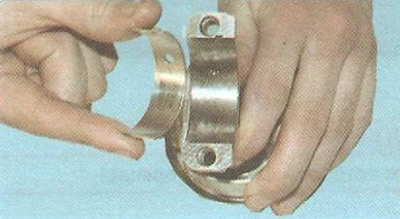
13. Install the bearing shells into the connecting rods, aligning the mounting tab on the bearing shell with the recess on the connecting rod.
14. Lubricate the cylinder bores, pistons, piston rings and connecting rod bearings with engine oil.
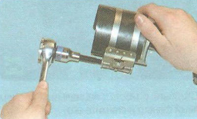
15. Install the ring compressor on the piston and tighten the screw to compress the rings.
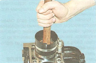
16. Turn the crankshaft so that its connecting rod journal, on which the connecting rod and piston group is mounted, is set to TDC. Install the piston in the cylinder in accordance with the cylinder number marking on the connecting rod, press (for example, with a hammer handle) onto the piston and slide it from the mandrel into the cylinder. Install the pistons into the remaining cylinders in the same way.
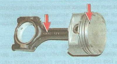
Note: When installing pistons into cylinders, mark (triangle) on the piston and the inscriptions on the connecting rod must face the front of the engine.
Warning: Install the piston into the cylinder carefully to avoid damaging the crankshaft journal with the connecting rod lower head.
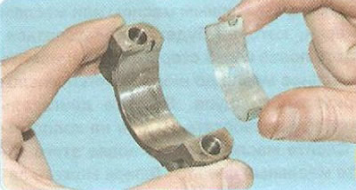
17. Install the connecting rod bearings into the connecting rod caps, aligning the mounting tab on the bearing with the recess on the cap.
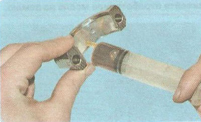
18. Lubricate the connecting rod bearings in the connecting rod caps and the connecting rod journals of the crankshaft with engine oil.
19. Install the connecting rod cap by connecting the connecting rod to the crankshaft journal and aligning the marks on the connecting rod and cap.
20. Screw in the connecting rod bolts without tightening them completely.
21. Tighten the connecting rod bolts until snug, but do not tighten them completely; then loosen them by one turn, tighten to a torque of 25 N·m (2.5 kgf·m) and tighten by 30°, and then by another 15°.
22. Check the ease of movement of the connecting rod along the crankpin. If jammed, unscrew the connecting rod bolts and re-tighten them to the rated torque.
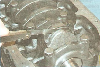
23. Check the connecting rod side clearance, it should be 0.070-0.242 mm. Increased clearance indicates excessive wear of the crankshaft crank cheeks. In this case, replace the crankshaft.
24. Secure the caps of the remaining connecting rods in the same way.
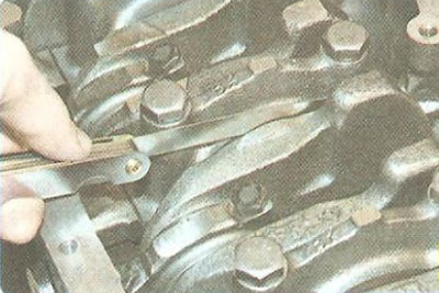
25. Check the axial clearance of the crankshaft, it should be 0.07-0.1 mm. An increased clearance indicates wear of the crankshaft support flanges or the bed of the middle main bearing. In this case, replace the crankshaft. If this does not lead to a decrease in axial clearance, you will have to replace the cylinder block.
26. Install the rear crankshaft oil seal (see "Replacing crankshaft seals").
27. Install the oil receiver and oil pump (see "Removal and installation the oil pump").
28. Install the oil pan (see "Replacing the oil pan seal").
29. Install the flywheel (see, "Removal, defect detection and installation of the flywheel").
30. Next, assemble the engine in the reverse order of disassembly. Installation of the cylinder head is described in the subsection "Replacing the cylinder head gasket", water pump - in the subsection "Replacing the water pump", timing belt - in the subsection "Replacing the timing belt and its tension roller".
Helpful advice: After assembling the engine, it is recommended to run it in on a stand. Since this cannot be done outside of special repair organizations, after installing the engine on the car, run it in using a simplified cycle in the following order.
1. Make sure the throttle actuator is adjusted correctly, fill with oil and coolant, check all connections for leaks.
2. Start the engine and let it run without load for the next cycle. Do not bring the engine to maximum operating modes.
| Crankshaft speed, min⁻¹ | Working time, min |
| 820-900 | 2 |
| 1000 | 3 |
| 1500 | 4 |
| 2000 | 5 |
3. During operation, check the tightness of the engine and its systems, oil pressure, pay attention to the presence of extraneous noises.
4. If any abnormal noise or other malfunctions are detected, stop the engine and eliminate the cause.
5. Once you start using the vehicle, follow the procedures provided for the break-in period of a new vehicle.
(The article is reprinted from the website: CHEVYMAN.ru)