ChevyMan.ru
Mazda Mitsubishi Toyota Land Rover Honda Kia Nissan
English Русский
Български
Беларускі
Український
Српски
Hrvatski
Română
Polski
Slovenský
Magyar
|
Articles | Sitemap | Contacts |


Home   Aveo   Captiva   Cruze   Lacetti   Lanos   Niva   Tahoe   Others  
Cruze 1 (2008-2016)
  • Home
  • Cruze
  • J300 (2008-2016)
  • Power unit
  • Engine repair
  • Removal and installation the engine

Removal and installation the engine (Chevrolet Cruze J300)

            0

The manufacturer recommends removing the power unit (engine with clutch and gearbox) down. To do this, you need a lift to raise the front of the car higher. In a garage, if you don't have a lift, you will need a jack, as well as strong and high enough supports to place the raised front of the car on them, which will make it possible to remove the engine from underneath it, lowered to the garage floor.

Helpful Hint: The engine is very heavy, so we recommend removing it with an assistant using special equipment (lift, hoist, etc.).


Warning: When removing and installing a power unit assembly that has a large mass, use only fully functional lifting mechanisms designed for the corresponding load, and especially carefully check the correctness and reliability of the connection of cables, crossbars, etc. to the engine transport eyes.


You will need: wrenches "10", "12", "14", "17", pliers, a flat-blade screwdriver.

1. For ease of work, remove the hood (see "Removal and installation the hood").

2. Reduce the pressure in the fuel system (see "Reducing pressure in the fuel system").

3. Remove the battery (see "Removal and installation the battery").

4. Drain the cooling system (see "Replacing the coolant").

5. If you remove the engine for repair, drain the oil from the oil pan (see "Changing engine oil and oil filter").
5. If you remove the engine for repair, drain the oil from the oil pan (see «Changing engine oil…


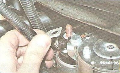
6. Unscrew the fastening nut...


6. Unscrew the fastening nut...


7. ...and disconnect the power wire from the contact bolt of the starter solenoid relay.
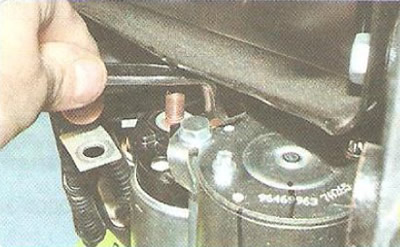
7. ...and disconnect the power wire from the contact bolt of the starter solenoid relay.


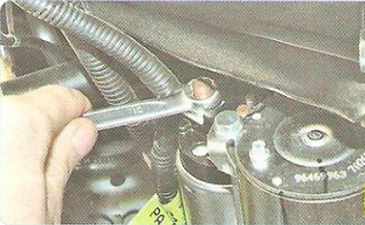
8. Unscrew the control wire mounting nut...
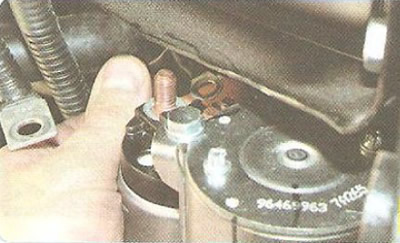
8. Unscrew the control wire mounting nut...


9. ...and disconnect the wire from the contact bolt of the traction relay.
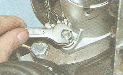
9. ...and disconnect the wire from the contact bolt of the traction relay.


10. Unscrew the nut...
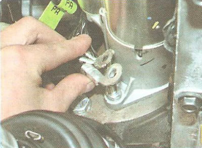


10. Unscrew the nut...


11. ...and remove the ground wire harnesses from the stud.
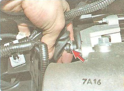
11. ...and remove the ground wire harnesses from the stud.


12. Unscrew the fastening nut and disconnect the wire from the generator contact bolt.
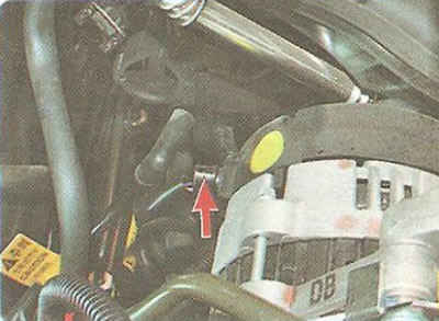
12. Unscrew the fastening nut and disconnect the wire from the generator contact bolt.


13. Disconnect the wiring harness connector from the voltage regulator.
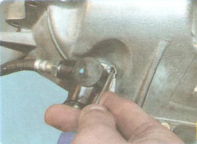
13. Disconnect the wiring harness connector from the voltage regulator.


14. Use a screwdriver to pry...
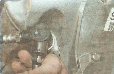


14. Use a screwdriver to pry...


15. ... remove the spring clip...
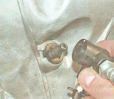
15. ... remove the spring clip...


16. ...and remove the clutch release hydraulic drive hose adapter from the end of the intermediate pipe.

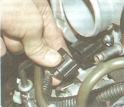
17. Disconnect the wiring harness connector from the throttle body connector (see "Removal and installation the throttle assembly").
17. Disconnect the wiring harness connector from the throttle body connector (see «Removal and…


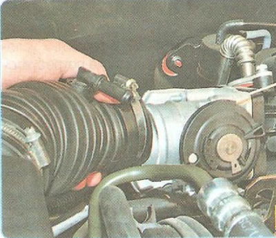
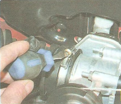
18. Loosen the clamp...

18. Loosen the clamp...


19. ...and remove the air supply hose from the throttle body neck (see "Removal and installation the air filter housing and intake noise muffler").


19. ...and remove the air supply hose from the throttle body neck (see «Removal and installation…


20. Press the lock and disconnect the wiring harness connector from the throttle assembly.
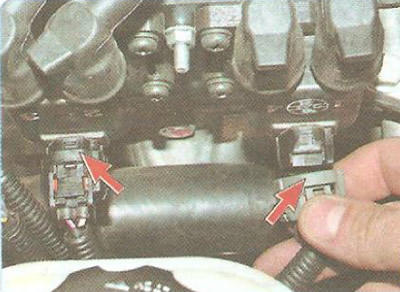
20. Press the lock and disconnect the wiring harness connector from the throttle assembly.


21. Release the clamps and disconnect the wiring harness connectors from the ignition coil...
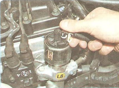
21. Release the clamps and disconnect the wiring harness connectors from the ignition coil...


22. ...and from the exhaust gas recirculation valve.
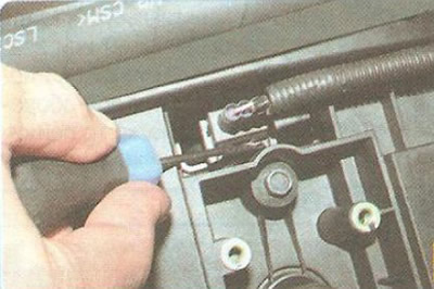
22. ...and from the exhaust gas recirculation valve.


23. Use a screwdriver to pry up the spring clip...
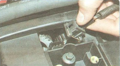


23. Use a screwdriver to pry up the spring clip...


24. ...and disconnect the wiring harness connector from the camshaft position sensor.
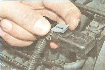
24. ...and disconnect the wiring harness connector from the camshaft position sensor.


25. Press the latch...
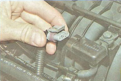
25. Press the latch...


26. ...and disconnect the wiring harness connector from the intake manifold vacuum sensor.
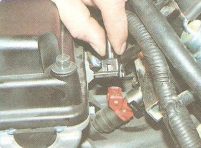
26. ...and disconnect the wiring harness connector from the intake manifold vacuum sensor.


27. Disconnect the wiring harness connectors from the injectors...
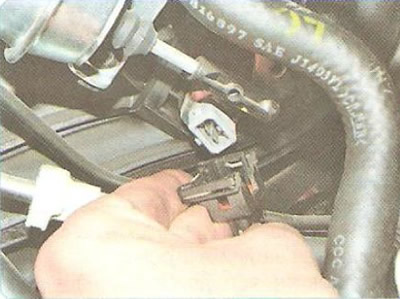
27. Disconnect the wiring harness connectors from the injectors...


28. ...and from the temperature sensor of the incoming air into the intake pipe.
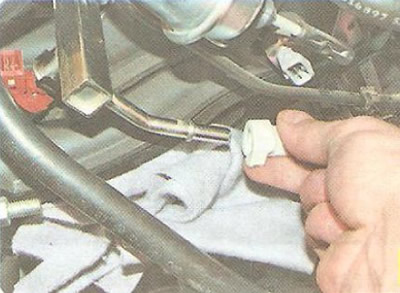
28. ...and from the temperature sensor of the incoming air into the intake pipe.


29. Squeeze the clamps and disconnect the fuel supply line from the fuel rail.
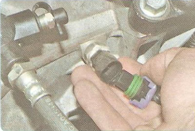
29. Squeeze the clamps and disconnect the fuel supply line from the fuel rail.


30. Disconnect the wiring harness connector from the reverse light switch...
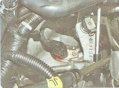
30. Disconnect the wiring harness connector from the reverse light switch...


31. ...from the speed sensor...
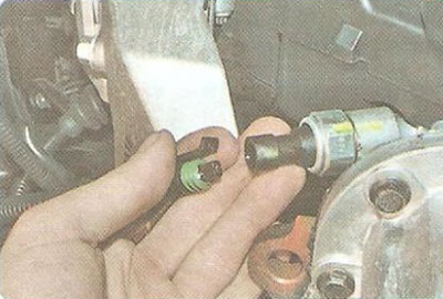
31. ...from the speed sensor...


32. ...and from the oil pressure drop warning light sensor.
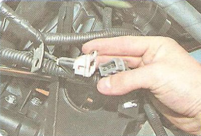
32. ...and from the oil pressure drop warning light sensor.


33. Disconnect the knock sensor wiring harness connector.
33. Disconnect the knock sensor wiring harness connector.


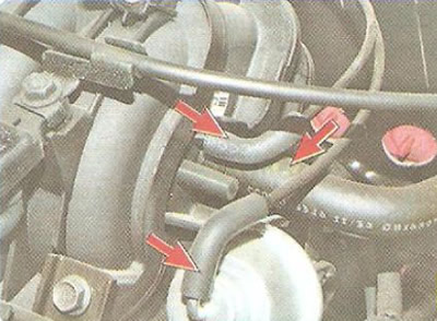
34. Disconnect the hoses of the intake manifold length adjustment system and the brake booster vacuum hose from the fittings.
34. Disconnect the hoses of the intake manifold length adjustment system and the brake booster…


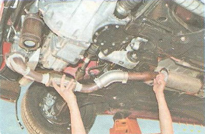
35. Remove the exhaust pipe (see "Replacing the inlet pipe").
35. Remove the exhaust pipe (see «Replacing the inlet pipe»).


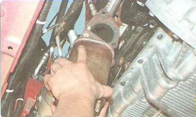
36. Remove the catalytic converter (see "Removal and installation the catalytic converter").
36. Remove the catalytic converter (see «Removal and installation the catalytic converter»).


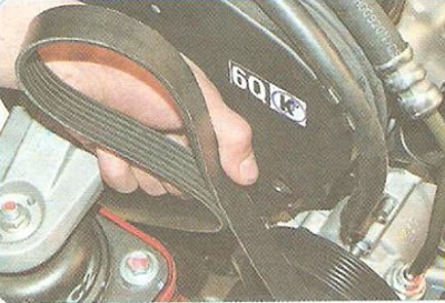
37. Remove the accessory drive belt (see "Replacement of auxiliary drive belt").
37. Remove the accessory drive belt (see «Replacement of auxiliary drive belt»).


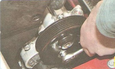
38. Loosen the two nuts securing the power steering pump by turning the pulley until the hole in it aligns with the nuts...
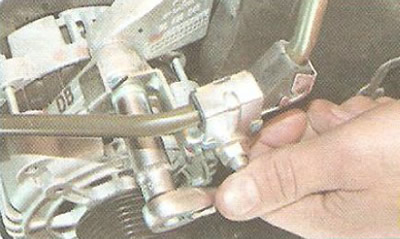
38. Loosen the two nuts securing the power steering pump by turning the pulley until the hole in it…


39. ...unscrew the nut securing the high-pressure line bracket of the power steering pump, remove the pump and move it to the side.
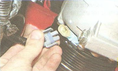
39. ...unscrew the nut securing the high-pressure line bracket of the power steering pump, remove…


40. Release the clips and disconnect the wiring harness connector from the air conditioning compressor.
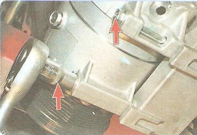
40. Release the clips and disconnect the wiring harness connector from the air conditioning…


41. Remove the two lower mounting bolts...
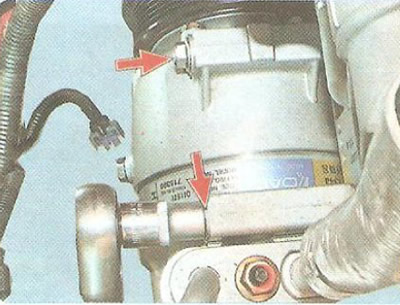
41. Remove the two lower mounting bolts...


42. ...and the two upper air conditioning compressor mounting bolts. Move the air conditioning compressor to the side without disconnecting the pipes from it, and secure it to the body using any available method (for example, tie it with wire).
42. ...and the two upper air conditioning compressor mounting bolts. Move the air conditioning…


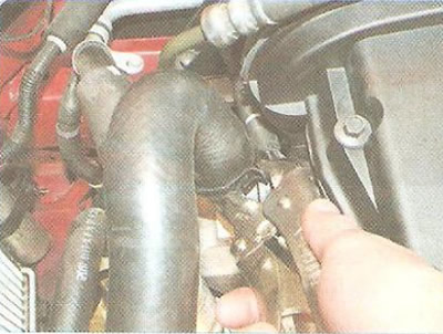
43. Loosen the clamp securing the radiator outlet hose of the cooling system by squeezing its bent ears, slide the clamp along the hose.
43. Loosen the clamp securing the radiator outlet hose of the cooling system by squeezing its bent…


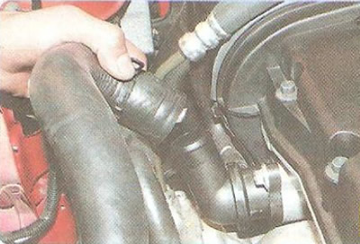
44. ...and remove the outlet hose from the thermostat housing pipe.
44. ...and remove the outlet hose from the thermostat housing pipe.


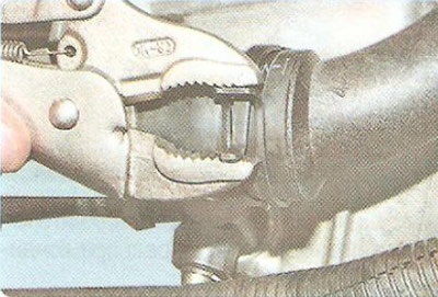
45. Loosen the clamp securing the radiator supply hose of the cooling system by squeezing its bent ears, slide the clamp along the hose...
45. Loosen the clamp securing the radiator supply hose of the cooling system by squeezing its bent…


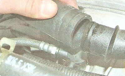
46. ...and remove the supply hose from the water distribution pipe.
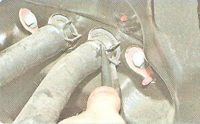
46. ...and remove the supply hose from the water distribution pipe.


47. Loosen the clamp securing the heater radiator outlet hose by squeezing its bent tabs, slide the clamp along the hose...
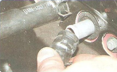
47. Loosen the clamp securing the heater radiator outlet hose by squeezing its bent tabs, slide the…


48. ...and disconnect the outlet hose from the heater radiator pipe. Disconnect the inlet hose in the same way.
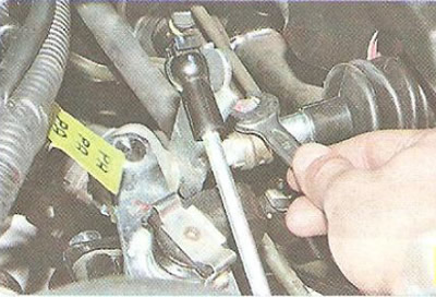
48. ...and disconnect the outlet hose from the heater radiator pipe. Disconnect the inlet hose in…


49. Loosen the transmission control drive terminal clamp bolt...
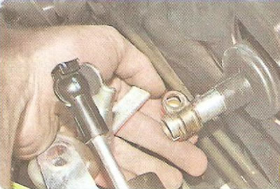
49. Loosen the transmission control drive terminal clamp bolt...


50. ...and disconnect the rod and gear shift lever.
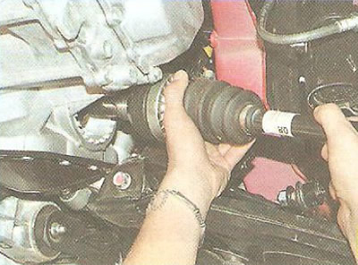
50. ...and disconnect the rod and gear shift lever.


51. Remove the front wheel drives (see "Removal and installation front wheel drives").

Note: The front wheel drives do not have to be disconnected from the gearbox. In this case, secure the drives disconnected from the hubs to the power unit using any available method (for example, tie it with wire).
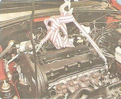

Note: The front wheel drives do not have to be disconnected from the gearbox. In this case, secure…


52. Attach the lifting gear slings to the front and rear transport eyes and tighten the slings.

53. Place a secure support under the engine.
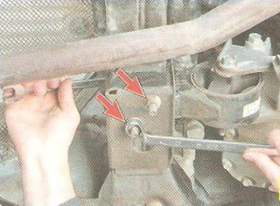
53. Place a secure support under the engine.


54. While holding the bolts securing the rear support cushion of the power unit from turning, use the second wrench to unscrew the nuts...
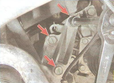
54. While holding the bolts securing the rear support cushion of the power unit from turning, use…


55. ...unscrew the three support bracket mounting bolts...
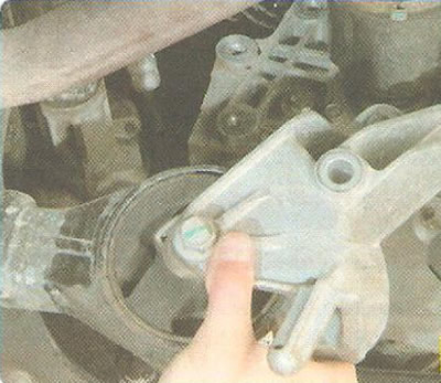
55. ...unscrew the three support bracket mounting bolts...


56. ...and remove the pillow.
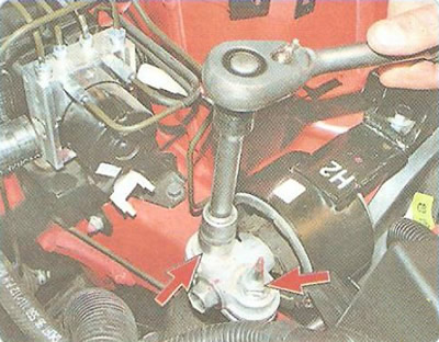
56. ...and remove the pillow.


57. Remove one bolt and one nut securing the power unit to the left support.

Note: Fuse box and battery tray removed for clarity.


58. Remove the right powertrain suspension support (see "Replacing the powertrain suspension mounts").

59. Check again that all wires, hoses and attachments are disconnected from the power unit.
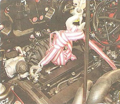
59. Check again that all wires, hoses and attachments are disconnected from the power unit.


60. Remove the support from under the engine and lower the power unit down to the floor.

61. Raise the front of the car (raise the car on a lift) to a height sufficient to remove the power unit from under the vehicle, and install reliable supports under the body.

62. Remove the power unit from under the vehicle.

63. Install the power unit, as well as all removed components and parts, in the reverse order of removal, taking into account the following:
  • before installing the power unit, use a tap to clean the threaded holes for mounting its supports from rust;
  • be sure to replace the intake manifold and neutralizer gaskets with new ones;
  • when connecting wires and pipes, carefully ensure that they are correctly positioned in the engine compartment, avoiding contact with heating and moving elements of the power unit.

After installing the engine, do the following.

1. Fill the engine with oil (see "Changing engine oil and oil filter").

2. Fill with coolant (see "Replacing the coolant").

3. Remove air from the clutch release hydraulic drive (see "Bleeding the clutch release hydraulic drive").

4. Start the engine and check for fuel, oil and coolant leaks. Check the oil pressure. Listen to the engine: it should run smoothly, without any extraneous noise or knocking.

The article was checked: Vladimir Romannikov
This article is available at russian, bulgarian, belarusian, ukrainian, serbian, croatian, romanian, polish, slovak, hungarian

Share information:

Previous articles
Cruze 1: Engine repair
Next articles

Lapping valves
Disassembly, repair and assembly of the cylinder head
Replacing hydraulic compensators
Removal, inspection and installation of camshafts
Replacing the exhaust manifold gasket
Disassembling the engine
Engine parts defect detection
Engine assembly
Design Features of F18D Engines
Checking and replacing the auxiliary drive belt of the F18D engine


See similar articles on the topic of Chevrolet cars:
The engine will not start Chevrolet Aveo T300 (2012-2018)
Engine coolant temperature gauge Chevrolet Captiva 1 (2006-2018)
Starting the engine from another car's battery («jump-starting») Chevrolet Lacetti 1 (2002-2009)
Starting the engine from another car's battery (jump-starting) Chevrolet Lanos T150 (2002-2009)
Starting the engine Chevrolet Niva 1 (2002-2016)
Starting a gasoline engine Chevrolet Tahoe 1 (1992-2000)
Engine bay and underbody of the car Chevrolet Lumina 1 (1989-1994)
Link in different formats to this page


Visitor comments

No comments yet


How much will 28 + 13 =


Cruze 1 (2008-2016) 
  • General information
  • User manual
  • Troubleshooting
  • Maintenance
  • Power unit
  • Engine repair
  • Lubrication system
  • Cooling system
  • Exhaust system
  • Supply system
  • Control system
  • Transmission
  • Clutch
  • Car gearbox
  • Front wheel drives
  • Chassis
  • Front suspension
  • Rear suspension
  • Steering
  • Brake system
  • Body
  • Exterior (external elements)
  • Interior (internal elements)
  • Doors, covers and windows
  • Heating and air conditioning
  • Security systems
  • Electrical equipment
  • Equipment and devices
  • Power devices
  • Lighting and signaling
  • Electrical circuits


ChevyMan.ru © 2017-2026 · Mobile version · Feedback · Site search · Interesting to read · Sitemap: EN BG BY UA RS HR RO PL SK HU

Aveo 2003-2008 · Aveo 2006-2011 · Aveo 2012-2018 · Captiva 2006-2018 · Cruze 2008-2016 · Lacetti 2002-2009 · Lanos 2002-2009 · Niva 2002-2016 · Tahoe 1992-2000 · Tahoe 2000-2014 · Lumina 1 1989-1994 · Trailblazer 1 2001-2008 · Orlando 1 2010-2018 ·
🛡️ For your security and to improve our service, this site uses cookies. You can disable them in your browser.