


- the pressure in the engine lubrication system has dropped. The cause of this malfunction is often increased wear of the camshaft journals and camshaft bearing seats in the cylinder head. If the seats are worn out, the cylinder head is replaced as an assembly, since the seats are made directly in its housing;
- valve knocking with serviceable hydraulic compensators of clearances in the valve drive mechanism. Caused by increased wear of the camshaft cams due to the use of low-quality motor oil or damage to the oil filter.
You will need: all the tools needed to remove the timing belt (see "Replacing the timing belt and its tension roller"), as well as a screwdriver and a micrometer.
1. Disconnect the wire from the negative terminal of the battery.
2. Remove the cylinder head cover (see "Replacing the cylinder head cover gasket").
3. Remove the air filter and disconnect the air supply pipe from the throttle assembly (see "Removal and installation the air filter housing and intake noise damper").
4. Remove the camshaft drive belt (see "Replacing the timing belt and its tension roller").
5. Remove the toothed pulleys from the intake and exhaust camshafts (see "Replacing camshaft seals").
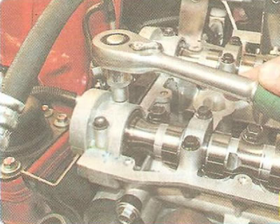
6. Remove two bolts securing the front camshaft bearing caps...
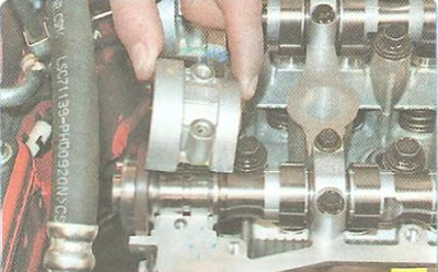
7. ... remove the covers...

8. ...and remove the camshaft seals.
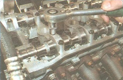
9. Unscrew the two bolts securing the remaining camshaft bearing caps, remove the caps...
Warning: Mark the covers in any way to ensure they are reinstalled in their original locations.
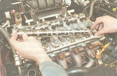
10. ...and remove the camshafts.
Warning: Mark the camshafts in any way so that they can be installed in their original positions during assembly.
11. Carefully inspect the surfaces of the camshaft bearing caps and the bearing journals on the cylinder head. If the bearing surfaces are excessively damaged, replace the cylinder head, since the bearing caps are machined together with the cylinder head and cannot be de-identified.
12. Carefully inspect the camshafts. There should be no damage or wear on the threads in the holes for fastening the toothed pulley. The surfaces of the bearing journals and cams should be well polished and without damage. No scoring, nicks, scratches, or aluminum drag from the bearing seats in the cylinder head are allowed on the working surfaces of the journals. If there are signs of seizure, overheating, deep scratches, or faceted wear on the working surfaces of the cams, replace the shaft.
Warning: Grinding the camshaft lobes to eliminate stepped wear is prohibited, since changing the cam profile dimensions will disrupt the valve timing.
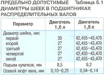
13. Measure the diameters of the bearing journals of the camshafts and their bearings, calculate the clearances in the shaft bearings, determined by the difference between the diameters of the bearings in the cylinder head and the diameters of the journals (Table 5.1). If wear exceeds the permissible limit, replace the camshaft, since regrinding of the journals to a repair size is not provided.
14. Install the camshafts and all removed parts in the reverse order of removal.
15. Adjust the timing belt tension (see "Checking timing belt").
(Information taken from the official website «chevyman»)