ChevyMan.ru
Mazda Mitsubishi Toyota Land Rover Honda Kia Nissan
English Русский
Български
Беларускі
Український
Српски
Hrvatski
Română
Polski
Slovenský
Magyar
|
Articles | Sitemap | Contacts |


Home   Aveo   Captiva   Cruze   Lacetti   Lanos   Niva   Tahoe   Others  
Aveo T300 (2012-2018) Aveo T250 (2006-2011) Aveo T200 (2003-2008)
  • Home
  • Aveo
  • T300 (2012-2018)
  • Power unit
  • Engine
  • Removal, inspection and installation of camshafts

Removal, inspection and installation of camshafts (Chevrolet Aveo T300)

            0

You will need: 24 mm wrenches, TORX T55, TORX E14, extension, ratchet.

1. Disconnect the wire from the negative terminal of the battery.
1. Disconnect the wire from the negative terminal of the battery.


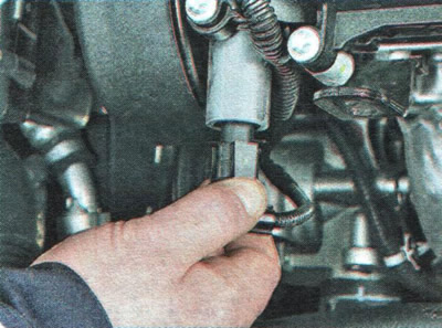
2. Press the lock...
2. Press the lock...


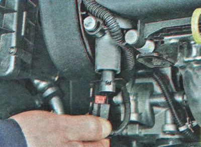
3. ...and disconnect the wiring harness connector from the electro-hydraulic valve of the exhaust camshaft.
3. ...and disconnect the wiring harness connector from the electro-hydraulic valve of the exhaust…


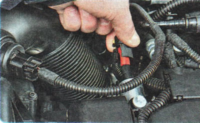
4. Similarly, disconnect the wiring harness connector from the electro-hydraulic valve of the intake camshaft.


4. Similarly, disconnect the wiring harness connector from the electro-hydraulic valve of the…


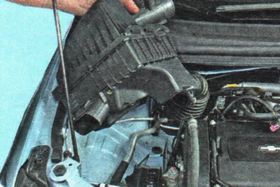
5. Remove the air filter housing (see "Removal and installation the air filter and air duct").
5. Remove the air filter housing (see «Removal and installation the air filter and air duct»).


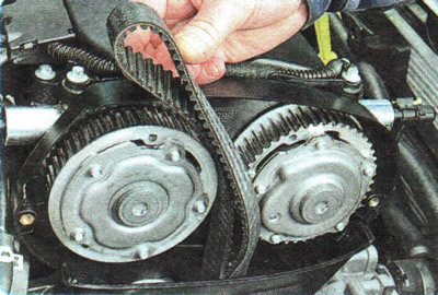
6. Remove the timing belt from the camshaft pulleys (see "Replacing the timing belt").
6. Remove the timing belt from the camshaft pulleys (see «Replacing the timing belt»).


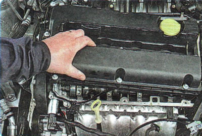
7. Remove the cylinder head cover (see "Replacing the cylinder head cover gasket").
7. Remove the cylinder head cover (see «Replacing the cylinder head cover gasket»).


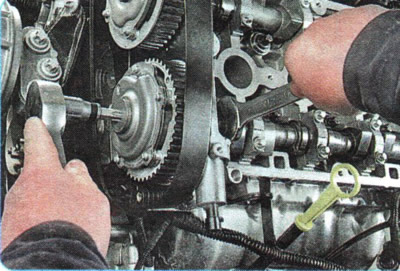
8. Using a wrench to hold the exhaust camshaft from turning, unscrew the toothed pulley mounting bolt plug...
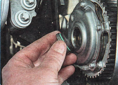


8. Using a wrench to hold the exhaust camshaft from turning, unscrew the toothed pulley mounting…


9. ...and remove the plug.

9. ...and remove the plug.


10. Similarly, unscrew and remove the plug of the intake camshaft.
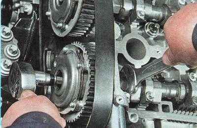
10. Similarly, unscrew and remove the plug of the intake camshaft.


11. While holding the exhaust camshaft from turning, remove the toothed pulley mounting bolt...
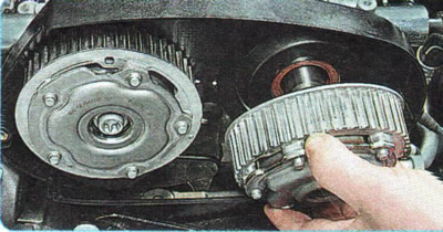
11. While holding the exhaust camshaft from turning, remove the toothed pulley mounting bolt...


12. ...and remove the pulley.
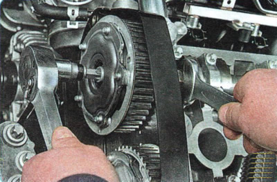


12. ...and remove the pulley.


13. Similarly, unscrew the bolt and remove the toothed pulley of the intake camshaft.
13. Similarly, unscrew the bolt and remove the toothed pulley of the intake camshaft.


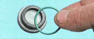
14. Replace the sealing gaskets of the camshaft toothed pulley bolt caps, regardless of their condition.
14. Replace the sealing gaskets of the camshaft toothed pulley bolt caps, regardless of their…


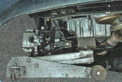
15. Place a jack or support under the engine crankcase.
15. Place a jack or support under the engine crankcase.


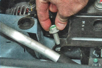
16. Unscrew the bolt...


16. Unscrew the bolt...


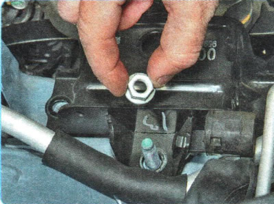
17. ...and unscrew the two nuts securing the right support of the power unit suspension to the body side member.
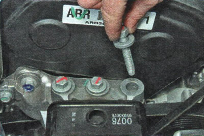
17. ...and unscrew the two nuts securing the right support of the power unit suspension to the body…


18. Remove the three bolts securing the support to the engine bracket...
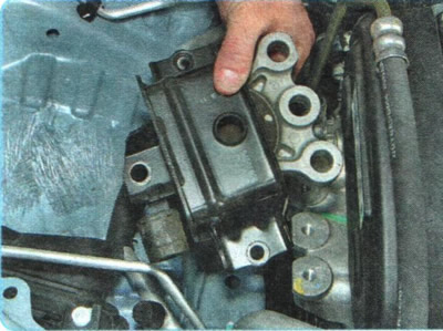
18. Remove the three bolts securing the support to the engine bracket...


19. ...and remove the support.
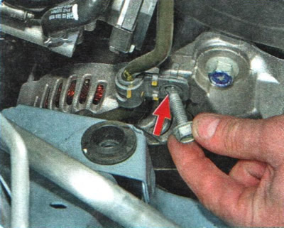
19. ...and remove the support.


20. Remove the bolt securing the power steering pipe holder to the support bracket.
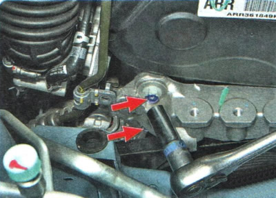


20. Remove the bolt securing the power steering pipe holder to the support bracket.


21. Remove the three bolts securing the bracket to the engine.
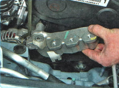
21. Remove the three bolts securing the bracket to the engine.


22. Remove the bracket.
22. Remove the bracket.


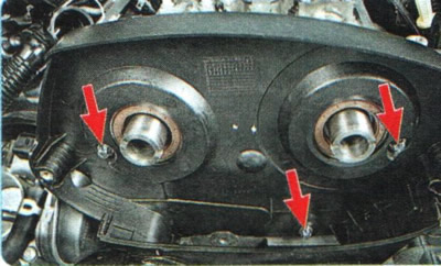
23. Remove the three upper bolts...
23. Remove the three upper bolts...


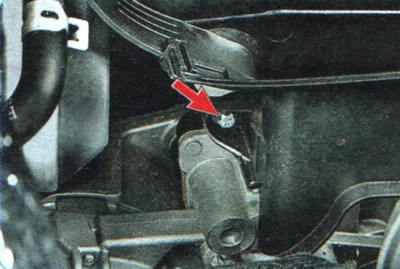
24. ...and one lower bolt securing the upper timing gear housing.
24. ...and one lower bolt securing the upper timing gear housing.


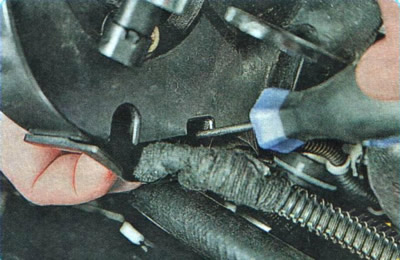
25. Overcoming the resistance of the clamps, disconnect the wiring harness holder from the upper casing.
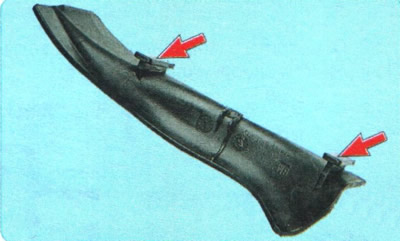
25. Overcoming the resistance of the clamps, disconnect the wiring harness holder from the upper…


NOTE: This is how the wiring harness retainer retaining clips are located.

NOTE: This is how the wiring harness retainer retaining clips are located.


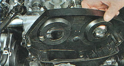
26. Remove the upper drive belt cover.
26. Remove the upper drive belt cover.


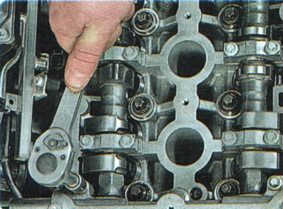
27. Remove the bolts securing the front camshaft bearing cover to the cylinder head...
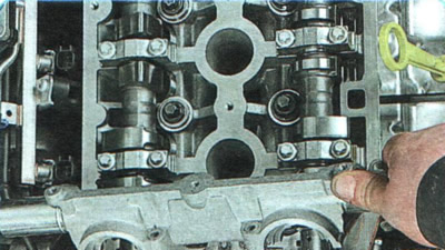
27. Remove the bolts securing the front camshaft bearing cover to the cylinder head...


28. ...and remove the lid.
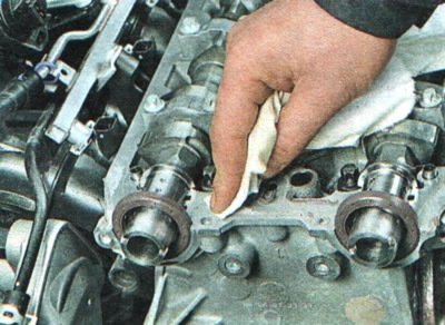
28. ...and remove the lid.


29. Clean the mating surfaces of the cylinder head...
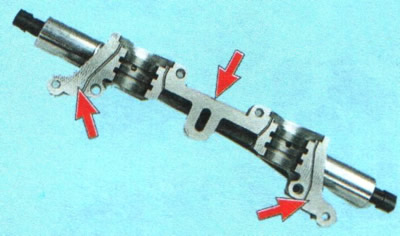
29. Clean the mating surfaces of the cylinder head...


30. ...and the front cover of the camshaft bearings.
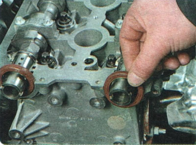
30. ...and the front cover of the camshaft bearings.


31. Remove the intake and exhaust camshaft oil seals from their seats in the cylinder head.
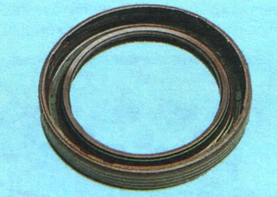
31. Remove the intake and exhaust camshaft oil seals from their seats in the cylinder head.


32. Replace the camshaft seals regardless of their condition.
32. Replace the camshaft seals regardless of their condition.


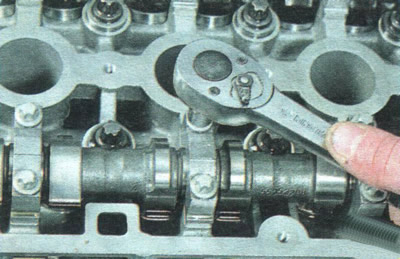
33. Loosen the exhaust camshaft bearing cap mounting bolts in the sequence shown in Figure 5.5.
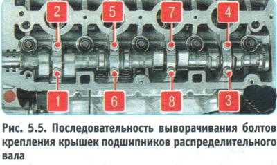
33. Loosen the exhaust camshaft bearing cap mounting bolts in the sequence shown in Figure 5.5.

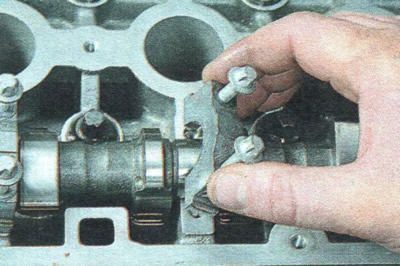
33. Loosen the exhaust camshaft bearing cap mounting bolts in the sequence shown in Figure 5.5.


34. Finally, unscrew the bolts, remove the camshaft bearing caps...
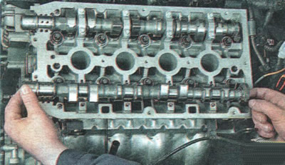
34. Finally, unscrew the bolts, remove the camshaft bearing caps...


35. ...and remove the exhaust camshaft.

36. Similarly, in the sequence shown in Figure 5.5, unscrew the bolts securing the intake camshaft covers, remove the covers...
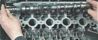
36. Similarly, in the sequence shown in Figure 5.5, unscrew the bolts securing the intake camshaft…


37. ...and then the intake camshaft.

37. ...and then the intake camshaft.
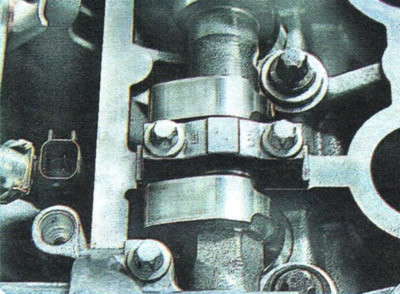

WARNING: The camshaft bearing caps are machined together with the cylinder head beds, so they must not be depersonalized. The bearing ordinal numbers are stamped on the caps. The numbers, made in the casting, are technological for the cap casting process and do not serve as a guide for installing the caps. Install the camshaft bearing caps in strict accordance with the markings applied to them.

WARNING: The camshaft bearing caps are machined together with the cylinder head beds, so they must…


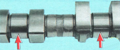
38. Inspect the camshafts. The bearing journal surfaces...
38. Inspect the camshafts. The bearing journal surfaces...


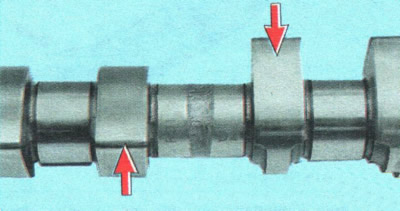
39. ...and the cams must be well polished and without damage. No scoring, nicks, scratches, or aluminum drag from the bearing seats in the cylinder head are allowed on the working surfaces of the journals. If signs of seizure, overheating, deep scratches, or faceted wear are found on the working surfaces of the cams, replace the shafts.

WARNING: Grinding the camshaft lobes to eliminate stepped wear is prohibited, since changing the cam profile dimensions will disrupt the valve timing.


40. In workshops equipped with special tools and devices, you can check the radial runout of the camshaft journals. If the runout is more than 0.02 mm or the journals are not aligned, replace the shaft, as its straightening is not allowed.

41. Lubricate the camshaft beds with clean engine oil and place the camshafts in them.

42. Install the camshaft bearing caps and tighten their mounting bolts evenly, moving from bolt to bolt through every other turn, in the sequence shown in Figure 5.6, to the torque specified in Appendix 1.
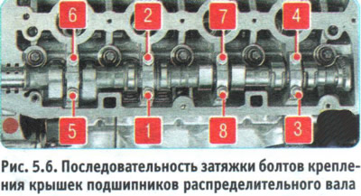
42. Install the camshaft bearing caps and tighten their mounting bolts evenly, moving from bolt to…


42. Install the camshaft bearing caps and tighten their mounting bolts evenly, moving from bolt to…


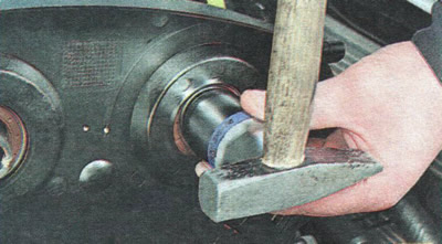
43. Press the exhaust and intake camshaft oil seals into the cylinder head sockets (see "Replacing camshaft seals").

44. Install the remaining removed parts in the reverse order of removal.

45. Adjust the valve clearances (see "Adjusting valve clearances").

The original source of the article is the website: CHEVYMAN.RU

The article was checked: Vladimir Romannikov
This article is available at russian, bulgarian, belarusian, ukrainian, serbian, croatian, romanian, polish, slovak, hungarian

Share information:

Previous articles
Aveo T300: Engine
Next articles

Adjusting valve clearances
Replacing the oil level indicator guide seal
Replacing camshaft seals
Replacing the oil pan seal
Replacing crankshaft seals
Lapping valves
Removal and installation of the power unit


See similar articles on the topic of Chevrolet cars:
Camshafts Chevrolet Captiva 1 (2006-2018)
Removal, inspection and installation of camshafts Chevrolet Cruze 1 (2008-2016)
Removal camshafts and hydraulic valve lifters Chevrolet Lacetti 1 (2002-2009)
Camshafts, rocker arms and clearance compensators — removal and installation Chevrolet Trailblazer 1 (2001-2008, petrol)
Link in different formats to this page


Visitor comments

No comments yet


How much will 29 + 19 =


Aveo T300 (2012-2018) 
  • General information
  • Vehicle device
  • User manual
  • Main malfunctions
  • Maintenance
  • Power unit
  • Engine
  • Lubrication system
  • Cooling system
  • Supply system
  • Exhaust system
  • Transmission
  • Clutch
  • Manual gearbox
  • Automatic gearbox
  • Front wheel drives
  • Chassis
  • Front suspension
  • Rear suspension
  • Steering
  • Brake system
  • Body
  • Exterior
  • Interior
  • Doors and trunk
  • Security systems
  • Electrical equipment
  • Engine electrics
  • Equipment and devices
  • Heating and air conditioning
  • Electrical circuits


Aveo T250 (2006-2011) 
  • Manual
  • Driver's workplace
  • Salon equipment
  • Vehicle characteristics
  • Maintenance
  • Engine 1.5 SOHC
  • Engine repair
  • Fuel supply system
  • Control system
  • Cooling system
  • Engine 1.6 DOHC
  • Engine repair
  • Control system
  • Transmission
  • Clutch
  • Manual gearbox
  • Automatic gearbox
  • Wheel drive
  • Chassis
  • Wheel suspension
  • Steering
  • Brake system
  • Body
  • Exterior
  • Interior


Aveo T200 (2003-2008) 
  • General information
  • User manual
  • Power unit
  • Engine repair 1.5L SOHC
  • Fuel system
  • Control system
  • Cooling system
  • Transmission
  • Clutch
  • Manual gearbox
  • Automatic gearbox
  • Drive shafts
  • Chassis
  • Front suspension
  • Rear suspension
  • Steering
  • Brake system
  • Body
  • Exterior (external elements)
  • Interior (internal elements)
  • Electrical equipment
  • Equipment and devices
  • Electrical circuits


ChevyMan.ru © 2017-2026 · Mobile version · Feedback · Site search · Interesting to read · Sitemap: EN BG BY UA RS HR RO PL SK HU

Aveo 2003-2008 · Aveo 2006-2011 · Aveo 2012-2018 · Captiva 2006-2018 · Cruze 2008-2016 · Lacetti 2002-2009 · Lanos 2002-2009 · Niva 2002-2016 · Tahoe 1992-2000 · Tahoe 2000-2014 · Lumina 1 1989-1994 · Trailblazer 1 2001-2008 · Orlando 1 2010-2018 ·
🛡️ For your security and to improve our service, this site uses cookies. You can disable them in your browser.