


Brake system of the car Chevrolet Aveo 1.5 (T250)

General information about the braking system
Hydraulic service brake system The hydraulic brake system of this car brakes all wheels. The front brakes are disc brakes with a floating caliper, in which the...
Hydraulic service brake system The hydraulic brake system of this car brakes all wheels. The front brakes are disc brakes with a floating caliper, in which the...

Brake system design (without ABS)
1. Filler plug of the feed tank of the hydraulic brake system. 2. Hydraulic system feed tank 3. Master brake cylinder (MBC) 4. Vacuum booster 5. Nut for...
1. Filler plug of the feed tank of the hydraulic brake system. 2. Hydraulic system feed tank 3. Master brake cylinder (MBC) 4. Vacuum booster 5. Nut for...

Brake system device (with ABS)
1. Filler plug of the feed tank of the hydraulic brake system 2. Hydraulic system feed tank 3. Master brake cylinder (MBC) 4. Vacuum booster 5. Nut for...
1. Filler plug of the feed tank of the hydraulic brake system 2. Hydraulic system feed tank 3. Master brake cylinder (MBC) 4. Vacuum booster 5. Nut for...
Front Disc Brake Specifications
Size, mm Minimum brake disc thickness 18 Brake disc runout 0,06 Brake disc diameter 236 (256*) Thickness of the new brake disc 20 (24*) Minimum permissible...
Size, mm Minimum brake disc thickness 18 Brake disc runout 0,06 Brake disc diameter 236 (256*) Thickness of the new brake disc 20 (24*) Minimum permissible...
Replacing the front brake pads
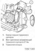
1. Raise the vehicle. 2. Mark the relative positions of the wheel and hub and remove the front wheels. 3. Remove the lower caliper guide mounting screw. When...
1. Raise the vehicle. 2. Mark the relative positions of the wheel and hub and remove the front wheels. 3. Remove the lower caliper guide mounting screw. When...

Removal and installation the brake caliper
1. Raise the vehicle. 2. Mark the position of the front wheels relative to the hubs and remove the wheels. 3. Remove the screws (2) securing the brake caliper...
1. Raise the vehicle. 2. Mark the position of the front wheels relative to the hubs and remove the wheels. 3. Remove the screws (2) securing the brake caliper...
Disassembling and assembling the brake caliper
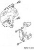
1. Remove the caliper assembly. 2. Loosen the caliper guide mounting screws and remove the caliper guides. 3. Remove the brake pads together with the springs....
1. Remove the caliper assembly. 2. Loosen the caliper guide mounting screws and remove the caliper guides. 3. Remove the brake pads together with the springs....

Replacing brake discs
Caution: Always replace both brake discs with new ones at the same time. 1. Remove the brake caliper assembly and secure it so that there is no load on the...
Caution: Always replace both brake discs with new ones at the same time. 1. Remove the brake caliper assembly and secure it so that there is no load on the...
Rear Drum Brake Specifications
Size, mm Inner diameter of brake drum 200 Maximum permissible internal diameter of the brake drum 201 Maximum permissible ovality 0,04 Minimum thickness of...
Size, mm Inner diameter of brake drum 200 Maximum permissible internal diameter of the brake drum 201 Maximum permissible ovality 0,04 Minimum thickness of...

Rear Drum Brake Adjustment
The clearance in the rear brake pads is self-adjusting. As the brake pads wear, the adjustment mechanism increases the clearance of the working stroke of the...
The clearance in the rear brake pads is self-adjusting. As the brake pads wear, the adjustment mechanism increases the clearance of the working stroke of the...

Replacing rear brake pads
1. Raise the vehicle. 2. Remove the rear wheels. 4. Loosen the parking brake cable. 5. Unscrew the nut (1) and remove the drum (2). When installing, tighten...
1. Raise the vehicle. 2. Remove the rear wheels. 4. Loosen the parking brake cable. 5. Unscrew the nut (1) and remove the drum (2). When installing, tighten...

Rear drum brake hydraulic cylinder diagram
1. Cap 2. Piston 3. Cuff 4. Spring cup 5. Hydraulic cylinder body 6. Air bleed valve 7. Spring
1. Cap 2. Piston 3. Cuff 4. Spring cup 5. Hydraulic cylinder body 6. Air bleed valve 7. Spring

Parking brake lever
1. Release the parking brake lever. 2. Move the front seats forward. 3. Remove the plugs from the holes and screws securing the parking brake console housing....
1. Release the parking brake lever. 2. Move the front seats forward. 3. Remove the plugs from the holes and screws securing the parking brake console housing....

Parking brake cables
1. Release the parking brake lever. 2. Remove the rear wheels. Remove the brake drums. 3. Remove the parking brake cable retaining ring from both sides of the...
1. Release the parking brake lever. 2. Remove the rear wheels. Remove the brake drums. 3. Remove the parking brake cable retaining ring from both sides of the...

Adjusting the parking brake
1. Adjust the rear drum brakes. 2. Release the parking brake. 3. Raise the car. 4. Check the parking brake cables for free movement. 5. Lower the vehicle. 6....
1. Adjust the rear drum brakes. 2. Release the parking brake. 3. Raise the car. 4. Check the parking brake cables for free movement. 5. Lower the vehicle. 6....

Master brake cylinder (MBC) — removal and installation
1. Disconnect the connector of the brake fluid level sensor (TA). 2. Disconnect the hydraulic pipes from the master cylinder (if the vehicle is not equipped...
1. Disconnect the connector of the brake fluid level sensor (TA). 2. Disconnect the hydraulic pipes from the master cylinder (if the vehicle is not equipped...

Removal and installation the expansion tank
1. Disconnect the connector of the brake fluid level sensor (TA). 2. On vehicles equipped with a manual transmission, disconnect the clutch release drive...
1. Disconnect the connector of the brake fluid level sensor (TA). 2. On vehicles equipped with a manual transmission, disconnect the clutch release drive...

Disassembly and assembly of the brake master cylinder
1. Remove the master cylinder. 2. Remove the expansion tank. 3. Remove the sealing ring from the master cylinder. Caution: When removing the retaining ring, be...
1. Remove the master cylinder. 2. Remove the expansion tank. 3. Remove the sealing ring from the master cylinder. Caution: When removing the retaining ring, be...

Brake pedal — removal and installation
1. Unscrew the screws securing the lower instrument panel trim cover. 2. Remove the trim cover. 3. Remove the brake light switch. 4. Remove the cotter pin from...
1. Unscrew the screws securing the lower instrument panel trim cover. 2. Remove the trim cover. 3. Remove the brake light switch. 4. Remove the cotter pin from...

Vacuum booster — removal and installation
1. On vehicles equipped with a manual transmission, disconnect the clutch release drive hydraulic system feed hose. Close the expansion tank and tube openings...
1. On vehicles equipped with a manual transmission, disconnect the clutch release drive hydraulic system feed hose. Close the expansion tank and tube openings...
Bleeding the hydraulic brake system
1. Press the brake pedal several times with the engine off until the pressure in the booster chamber equalizes with atmospheric pressure (the vacuum should be...
1. Press the brake pedal several times with the engine off until the pressure in the booster chamber equalizes with atmospheric pressure (the vacuum should be...
Anti-lock braking system (ABS)
The anti-lock braking system (ABS) is designed to provide the maximum possible braking intensity under specific road conditions (and therefore, minimal braking...
The anti-lock braking system (ABS) is designed to provide the maximum possible braking intensity under specific road conditions (and therefore, minimal braking...

ABS system components
1. Hydraulic unit of the ABS system 2. ABS hydraulic unit mounting bracket 3. Front wheel speed sensor 4. Rear wheel speed sensor ABS hydraulic unit diagram
1. Hydraulic unit of the ABS system 2. ABS hydraulic unit mounting bracket 3. Front wheel speed sensor 4. Rear wheel speed sensor ABS hydraulic unit diagram
This section is available at russian, bulgarian, belarusian, ukrainian, serbian, croatian, romanian, polish, slovak, hungarian
See similar sections on Chevrolet cars:
Chassis: Brake system Chevrolet Captiva 1 (2006-2018)
Chassis: Brake system Chevrolet Cruze 1 (2008-2016)
Chassis: Brake system Chevrolet Lacetti 1 (2002-2009)
Chassis: Brake system Chevrolet Lanos T150 (2002-2009)
Chassis: Brake system Chevrolet Niva 1 (2002-2016)
Chassis: Brake system Chevrolet Tahoe 1 (1992-2000)
Chassis: Brake system Chevrolet Trailblazer 1 (2001-2008, petrol)
Chassis: Brake system Chevrolet Captiva 1 (2006-2018)
Chassis: Brake system Chevrolet Cruze 1 (2008-2016)
Chassis: Brake system Chevrolet Lacetti 1 (2002-2009)
Chassis: Brake system Chevrolet Lanos T150 (2002-2009)
Chassis: Brake system Chevrolet Niva 1 (2002-2016)
Chassis: Brake system Chevrolet Tahoe 1 (1992-2000)
Chassis: Brake system Chevrolet Trailblazer 1 (2001-2008, petrol)
Share information:
- General information
- Vehicle device
- User manual
- Main malfunctions
- Maintenance
- Power unit
- Engine
- Lubrication system
- Cooling system
- Supply system
- Exhaust system
- Transmission
- Clutch
- Manual gearbox
- Automatic gearbox
- Front wheel drives
- Chassis
- Front suspension
- Rear suspension
- Steering
- Brake system
- Body
- Exterior
- Interior
- Doors and trunk
- Security systems
- Electrical equipment
- Engine electrics
- Equipment and devices
- Heating and air conditioning
- Electrical circuits
- Manual
- Driver's workplace
- Salon equipment
- Vehicle characteristics
- Maintenance
- Engine 1.5 SOHC
- Engine repair
- Fuel supply system
- Control system
- Cooling system
- Engine 1.6 DOHC
- Engine repair
- Control system
- Transmission
- Clutch
- Manual gearbox
- Automatic gearbox
- Wheel drive
- Chassis
- Wheel suspension
- Steering
- Brake system
- Body
- Exterior
- Interior
- General information
- User manual
- Power unit
- Engine repair 1.5L SOHC
- Fuel system
- Control system
- Cooling system
- Transmission
- Clutch
- Manual gearbox
- Automatic gearbox
- Drive shafts
- Chassis
- Front suspension
- Rear suspension
- Steering
- Brake system
- Body
- Exterior (external elements)
- Interior (internal elements)
- Electrical equipment
- Equipment and devices
- Electrical circuits