ChevyMan.ru
Mazda Mitsubishi Toyota Land Rover Honda Kia Nissan
English Русский
Български
Беларускі
Український
Српски
Hrvatski
Română
Polski
Slovenský
Magyar
|
Articles | Sitemap | Contacts |


Home   Aveo   Captiva   Cruze   Lacetti   Lanos   Niva   Tahoe   Others  
Aveo T300 (2012-2018) Aveo T250 (2006-2011) Aveo T200 (2003-2008)
  • Home
  • Aveo
  • T300 (2012-2018)
  • Power unit
  • Engine
  • Removal and installation of the power unit

Removal and installation of the power unit (Chevrolet Aveo T300)

            0

You will need: keys "10", "13", "18", TORXT30, socket heads "10", "13", "15", TORX E10, E14, E18, extension, ratchet, screwdrivers with flat and Phillips blades, pliers with sliding grip.

The manufacturer recommends removing the power unit (engine with gearbox) down. To do this, you need a lift to raise the front of the car higher. In a garage, if you don't have a lift, you will need a jack, as well as strong and high enough supports to place the raised front of the car on. This will allow you to remove the engine from underneath it, which is lowered to the garage floor.

USEFUL TIP: The engine is very heavy, so we recommend removing it with an assistant and using special equipment (lift, hoist, etc.).


WARNING: When removing and installing a heavy power unit assembly, use only fully functional lifting equipment designed for the corresponding load, and especially carefully check the correctness and reliability of the connection of cables, crossbars, etc. to the engine transport eyes.


1. Remove the battery.
1. Remove the battery.


2. Remove the battery mounting shelf (see "Removal and installation the battery mounting shelf").


3. Drain the oil from the engine (see "Changing engine oil and oil filter").
3. Drain the oil from the engine (see «Changing engine oil and oil filter»).


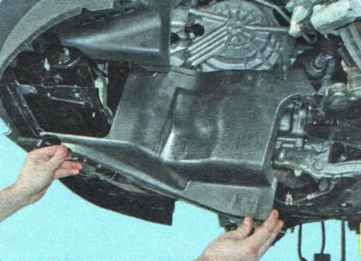
4. Remove the mudguards and engine crankcase protection (see "Removal and installation mudguards and engine crankcase protection").

5. Drain the cooling system (see "Replacing the coolant").
5. Drain the cooling system (see «Replacing the coolant»).


6. Press the lock...

6. Press the lock...


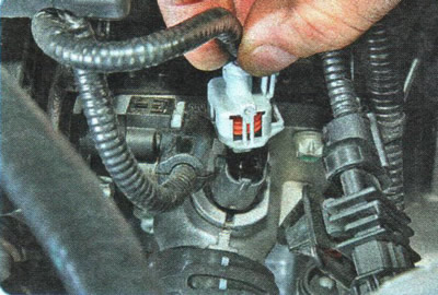
7. ...and disconnect the wiring harness connector from the electro-hydraulic valve of the exhaust camshaft.


7. ...and disconnect the wiring harness connector from the electro-hydraulic valve of the exhaust…


8. Similarly, disconnect the wiring harness connector from the electro-hydraulic valve of the intake camshaft.
8. Similarly, disconnect the wiring harness connector from the electro-hydraulic valve of the…


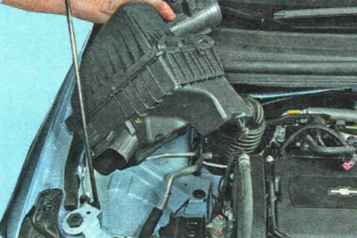
9. Remove the air filter (see "Removal and installation the air filter and air duct").
9. Remove the air filter (see «Removal and installation the air filter and air duct»).


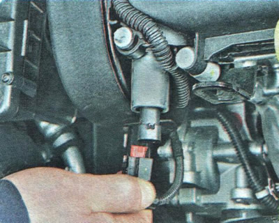
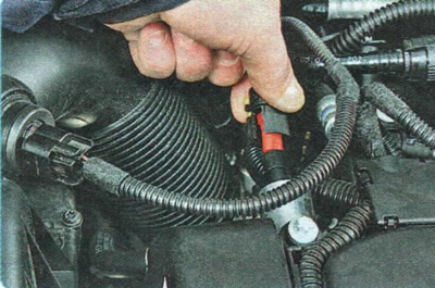
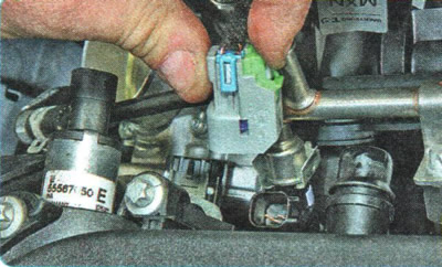
10. Press the release button and disconnect the wiring harness connector from the thermostat heating element.


10. Press the release button and disconnect the wiring harness connector from the thermostat…


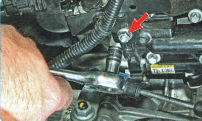
11. Unscrew the nut securing the engine compartment wiring harness bracket.
11. Unscrew the nut securing the engine compartment wiring harness bracket.


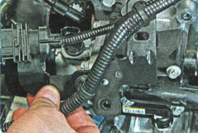
12. Remove the bracket from the stud and move the wiring harness to the side.
12. Remove the bracket from the stud and move the wiring harness to the side.


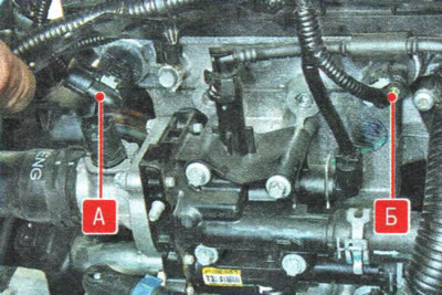
13. Disconnect the wiring harness connectors from the exhaust camshaft position sensor A and the intake camshaft position sensor B.
13. Disconnect the wiring harness connectors from the exhaust camshaft position sensor A and the…


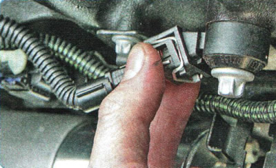
14. Disconnect the wiring harness connectors from the fuel injectors.


14. Disconnect the wiring harness connectors from the fuel injectors.


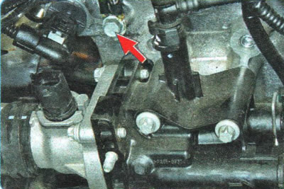
15. Unscrew the bolt securing the negative wire tip to the cylinder head and move the tip to the side.
15. Unscrew the bolt securing the negative wire tip to the cylinder head and move the tip to the…


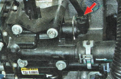
16. Press the lock and disconnect the wiring harness connector from the coolant temperature sensor.
16. Press the lock and disconnect the wiring harness connector from the coolant temperature sensor.


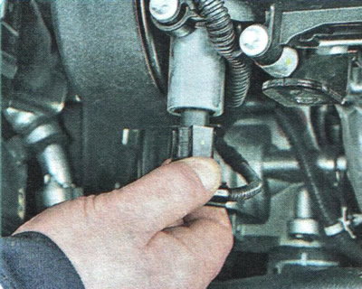
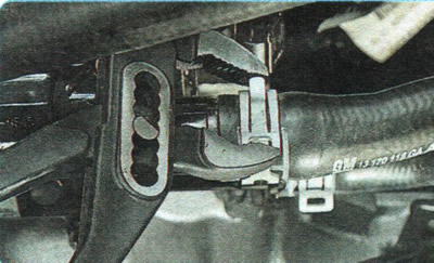
17. Disconnect the wiring harness connector from the knock sensor.
17. Disconnect the wiring harness connector from the knock sensor.


18. Loosen the heater hose clamps by squeezing their bent tabs with pliers. Slide the clamps along the hoses...
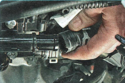


18. Loosen the heater hose clamps by squeezing their bent tabs with pliers. Slide the clamps along…


19. ...and disconnect the hoses from the pipes.
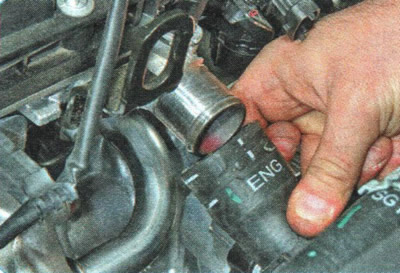
19. ...and disconnect the hoses from the pipes.


20. Similarly, loosen the clamp securing the hose to the thermostat pipe and disconnect the hose from the pipe.
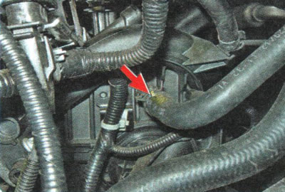
20. Similarly, loosen the clamp securing the hose to the thermostat pipe and disconnect the hose…


21. Loosen the brake booster vacuum hose clamp by squeezing its bent tabs with pliers. Slide the clamp along the hose and disconnect the hose from the inlet pipe fitting.
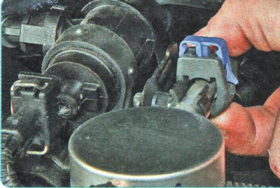
21. Loosen the brake booster vacuum hose clamp by squeezing its bent tabs with pliers. Slide the…


22. Use a screwdriver to pry up and slide out the plastic retainer...
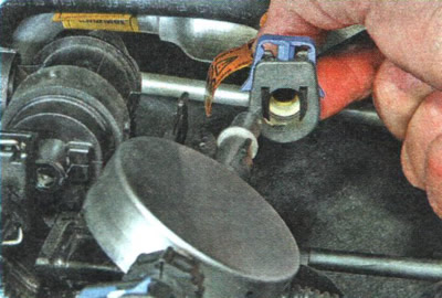
22. Use a screwdriver to pry up and slide out the plastic retainer...


23. ...press the stopper and disconnect the fuel hose tip from the pulsation compensator.
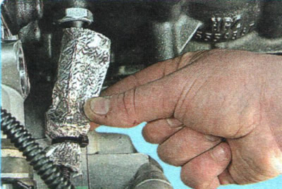
23. ...press the stopper and disconnect the fuel hose tip from the pulsation compensator.


24. Slide the heat shield along the wire harness.
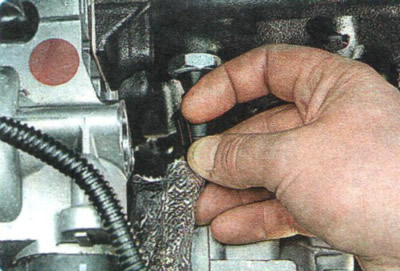
24. Slide the heat shield along the wire harness.


25. Press the lock of the wiring harness connector...
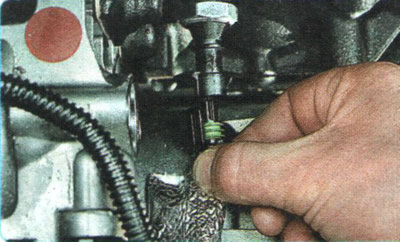
25. Press the lock of the wiring harness connector...


26. ...and disconnect the connector from the oil pressure sensor.
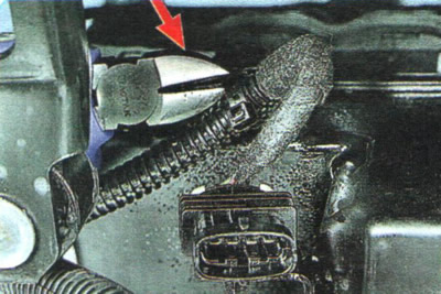
26. ...and disconnect the connector from the oil pressure sensor.


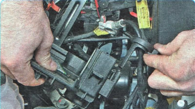
27. Disconnect the plastic holders of the engine wiring harness from the engine brackets by cutting them with nippers.

28. Remove the wiring harness from the engine compartment.
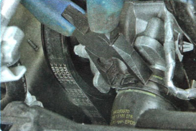
28. Remove the wiring harness from the engine compartment.


29. Squeeze the bent ears of the clamp securing the radiator outlet hose to the water pump pipe, slide the clamp along the hose...
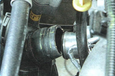
29. Squeeze the bent ears of the clamp securing the radiator outlet hose to the water pump pipe,…


30. ...and remove the hose from the branch pipe.
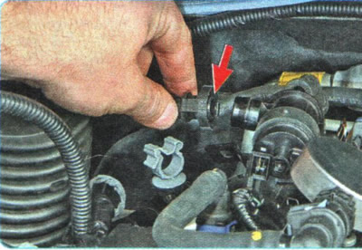
30. ...and remove the hose from the branch pipe.


31. Squeeze the locking device of the steam line tip and disconnect the tip from the nipple of the purge valve of the adsorber.
31. Squeeze the locking device of the steam line tip and disconnect the tip from the nipple of the…


32. Press the lock of the wiring harness connector...
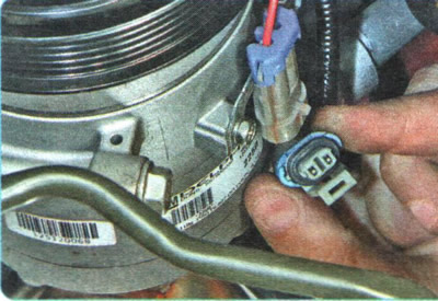
32. Press the lock of the wiring harness connector...


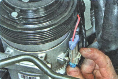
33. ...and disconnect the connector from the air conditioning compressor electromagnetic clutch connector.
33. ...and disconnect the connector from the air conditioning compressor electromagnetic clutch…


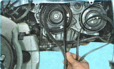
34. Remove the accessory drive belts (see "Replacement of auxiliary drive belts").
34. Remove the accessory drive belts (see «Replacement of auxiliary drive belts»).


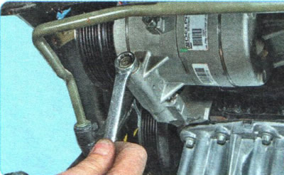
35. Unscrew the air conditioning compressor mounting bolts, move the compressor to the side without disconnecting the hoses from it, and secure the compressor to the body with wire, preventing the hoses from twisting or being pulled.
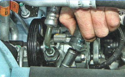
35. Unscrew the air conditioning compressor mounting bolts, move the compressor to the side without…


36. Disconnect the return line from the power steering pump...
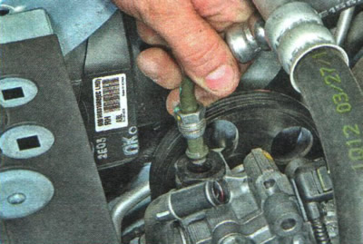
36. Disconnect the return line from the power steering pump...


37. ...and pressure pipelines (see "Removal and installation the power steering pump").
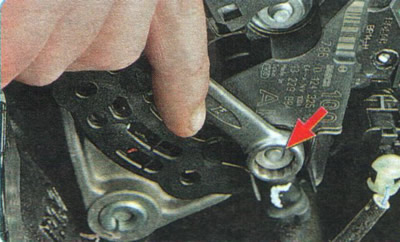
37. ...and pressure pipelines (see «Removal and installation the power steering pump»).


38. Unscrew the nut securing the power cable tip and disconnect the cable from the generator terminal.
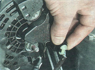
38. Unscrew the nut securing the power cable tip and disconnect the cable from the generator…


39. Press the clamp of the voltage regulator wiring harness connector...
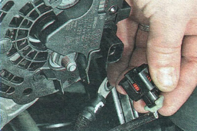
39. Press the clamp of the voltage regulator wiring harness connector...


40. ...and disconnect the block from the regulator.
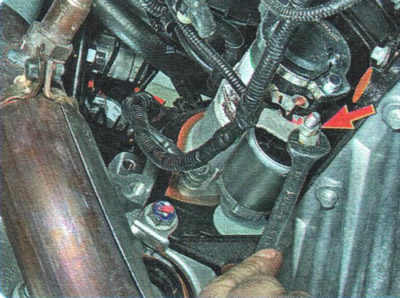
40. ...and disconnect the block from the regulator.


41. Unscrew the power cable fastening nut...
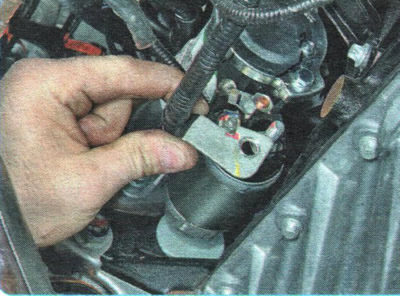
41. Unscrew the power cable fastening nut...


42. ...and remove the wire from the contact bolt of the traction relay.
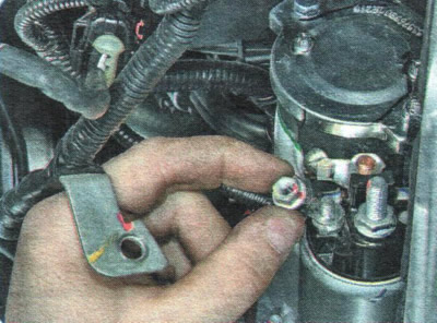
42. ...and remove the wire from the contact bolt of the traction relay.


43. Unscrew the nut securing the control wire of the traction relay.
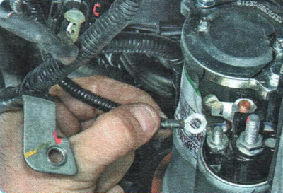
43. Unscrew the nut securing the control wire of the traction relay.


44. Remove the control wire from the contact bolt of the traction relay and move the removed wires to the side.
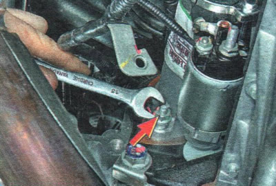
44. Remove the control wire from the contact bolt of the traction relay and move the removed wires…


45. Unscrew the nut securing the ground wire.
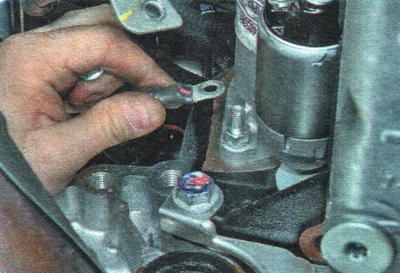
45. Unscrew the nut securing the ground wire.


46. Remove the ground wire from the lower starter mounting stud and move it to the side.

47. Disconnect the control cables and sensor wiring harness connectors from the gearbox (see "Removal and installation of a manual gearbox" or "Removal and installation of automatic transmission").
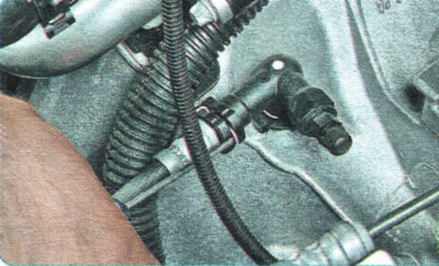
47. Disconnect the control cables and sensor wiring harness connectors from the gearbox (see…


48. On a car with a manual transmission, use a screwdriver to pry...
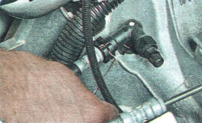
48. On a car with a manual transmission, use a screwdriver to pry...


49. ...pull the retainer out of the clutch release line adapter...
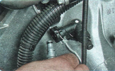
49. ...pull the retainer out of the clutch release line adapter...


50. ...and remove the hose tip from the adapter.
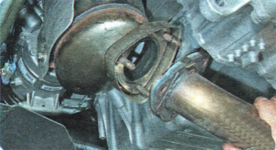
50. ...and remove the hose tip from the adapter.


51. Remove the exhaust pipe (see "Replacing the inlet pipe").
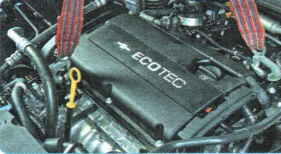
51. Remove the exhaust pipe (see «Replacing the inlet pipe»).


52. Attach the engine to the special lugs and tighten the sling (for example, a crane, a hoist or other lifting mechanism).
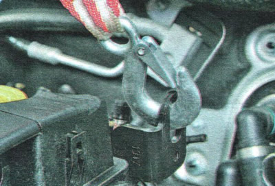
52. Attach the engine to the special lugs and tighten the sling (for example, a crane, a hoist or…


WARNING: Make sure the sling is securely fastened to the lifting eyes.

WARNING: Make sure the sling is securely fastened to the lifting eyes.


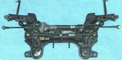
53. Remove the front suspension crossmember (see "Removal and installation the front suspension crossmember").
53. Remove the front suspension crossmember (see «Removal and installation the front suspension…


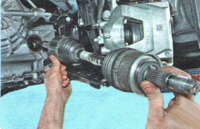
54. Remove the front wheel drives (see "Removal and installation front wheel drives").

55. Place reliable supports under the power unit (it is best to use a trolley with a lifting capacity of at least 300 kg).

56. Lower the front of the vehicle so that the power unit rests on a support or dolly.

57. Check that all wires attached to the body are disconnected from the power unit. Check that hoses, tubes and body components do not interfere with the removal of the power unit downwards.
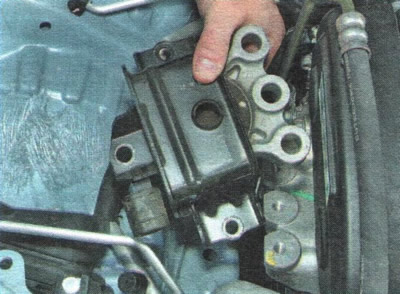
57. Check that all wires attached to the body are disconnected from the power unit. Check that…


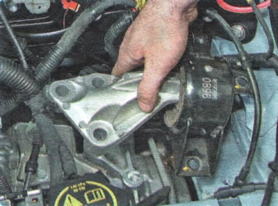
58. Remove the right...

58. Remove the right...


59. ...and the left support of the power unit suspension (see "Replacing the powertrain suspension mounts").

60. Raise the front of the car (raise the car on a lift) to a height sufficient to remove the power unit from under the vehicle, and install reliable supports under the body.

61. Remove the power unit from under the vehicle.

62. Install the power unit, as well as all removed units and parts in the reverse order of removal. When connecting wires and pipes, carefully monitor their correct location in the engine compartment, preventing contact with heating and moving elements of the power unit.

63. Fill the engine with oil (see "Changing engine oil and oil filter").

64. Fill with coolant (see "Replacing the coolant").

65. On a vehicle with a manual transmission, bleed the air from the clutch release hydraulic drive (see "Bleeding the clutch release hydraulic drive").

66. Start the engine and check for fuel, oil and coolant leaks. Check the oil pressure. Listen to the engine: it should run smoothly, without any extraneous noise or knocking.

The article was checked: Vladimir Romannikov
This article is available at russian, bulgarian, belarusian, ukrainian, serbian, croatian, romanian, polish, slovak, hungarian

Share information:

Previous articles
Aveo T300: Engine
Next articles

Lapping valves
Removal, inspection and installation of camshafts
Adjusting valve clearances
Replacing the oil level indicator guide seal
Replacing camshaft seals


See similar articles on the topic of Chevrolet cars:
Remote control unit Chevrolet Captiva 1 (2006-2018)
Starting the engine from external power sources Chevrolet Cruze 1 (2008-2016)
Checking the level of working fluid in the power steering reservoir Chevrolet Lacetti 1 (2002-2009)
Heating, ventilation and air conditioning control unit Chevrolet Lanos T150 (2002-2009)
Power steering Chevrolet Niva 1 (2002-2016)
Dismantling the power unit — safety measures Chevrolet Tahoe 1 (1992-2000)
Check Power Steering Fluid (Every 3,000 miles or 3 months) Chevrolet Lumina 1 (1989-1994)
Link in different formats to this page


Visitor comments

No comments yet


How much will 34 + 11 =


Aveo T300 (2012-2018) 
  • General information
  • Vehicle device
  • User manual
  • Main malfunctions
  • Maintenance
  • Power unit
  • Engine
  • Lubrication system
  • Cooling system
  • Supply system
  • Exhaust system
  • Transmission
  • Clutch
  • Manual gearbox
  • Automatic gearbox
  • Front wheel drives
  • Chassis
  • Front suspension
  • Rear suspension
  • Steering
  • Brake system
  • Body
  • Exterior
  • Interior
  • Doors and trunk
  • Security systems
  • Electrical equipment
  • Engine electrics
  • Equipment and devices
  • Heating and air conditioning
  • Electrical circuits


Aveo T250 (2006-2011) 
  • Manual
  • Driver's workplace
  • Salon equipment
  • Vehicle characteristics
  • Maintenance
  • Engine 1.5 SOHC
  • Engine repair
  • Fuel supply system
  • Control system
  • Cooling system
  • Engine 1.6 DOHC
  • Engine repair
  • Control system
  • Transmission
  • Clutch
  • Manual gearbox
  • Automatic gearbox
  • Wheel drive
  • Chassis
  • Wheel suspension
  • Steering
  • Brake system
  • Body
  • Exterior
  • Interior


Aveo T200 (2003-2008) 
  • General information
  • User manual
  • Power unit
  • Engine repair 1.5L SOHC
  • Fuel system
  • Control system
  • Cooling system
  • Transmission
  • Clutch
  • Manual gearbox
  • Automatic gearbox
  • Drive shafts
  • Chassis
  • Front suspension
  • Rear suspension
  • Steering
  • Brake system
  • Body
  • Exterior (external elements)
  • Interior (internal elements)
  • Electrical equipment
  • Equipment and devices
  • Electrical circuits


ChevyMan.ru © 2017-2026 · Mobile version · Feedback · Site search · Interesting to read · Sitemap: EN BG BY UA RS HR RO PL SK HU

Aveo 2003-2008 · Aveo 2006-2011 · Aveo 2012-2018 · Captiva 2006-2018 · Cruze 2008-2016 · Lacetti 2002-2009 · Lanos 2002-2009 · Niva 2002-2016 · Tahoe 1992-2000 · Tahoe 2000-2014 · Lumina 1 1989-1994 · Trailblazer 1 2001-2008 · Orlando 1 2010-2018 ·
🛡️ For your security and to improve our service, this site uses cookies. You can disable them in your browser.