ChevyMan.ru
Mazda Mitsubishi Toyota Land Rover Honda Kia Nissan
English Русский
Български
Беларускі
Український
Српски
Hrvatski
Română
Polski
Slovenský
Magyar
|
Articles | Sitemap | Contacts |


Home   Aveo   Captiva   Cruze   Lacetti   Lanos   Niva   Tahoe   Others  
Aveo T300 (2012-2018) Aveo T250 (2006-2011) Aveo T200 (2003-2008)
  • Home
  • Aveo
  • T300 (2012-2018)
  • Transmission
  • Front wheel drives
  • Removal and installation front wheel drives

Removal and installation front wheel drives (Chevrolet Aveo T300)

            0

You will need: a 36 mm socket head, a wrench and a 15 mm socket head, a mounting blade, a hammer, a thin chisel, a punch, a soft metal drift or a wooden spacer.

Front wheel drives are removed for replacement if damaged or for replacement of joints and their covers. In addition, front wheel drives may need to be removed to gain access to other units.

NOTE: The removal and installation procedure is shown using the left front wheel drive as an example. The right front wheel drive is removed and installed in the same way.


1. Remove the mudguards and engine sump guard, if installed on the vehicle (see "Removal and installation mudguards and engine crankcase protection").

2. Drain the oil from the manual transmission (see "Checking the level, topping up and replacing oil in a manual transmission") or working fluid from an automatic transmission (see "Checking the level, topping up and replacing the working fluid in the automatic transmission").
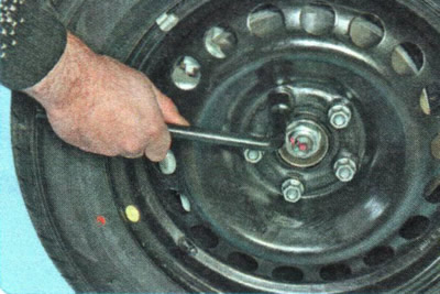
2. Drain the oil from the manual transmission (see «Checking the level, topping up and replacing…


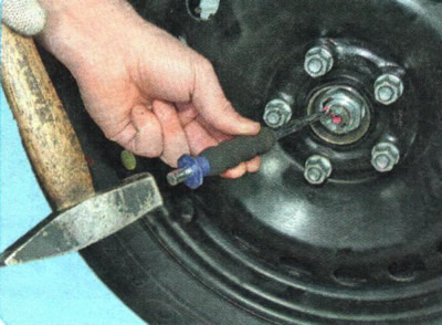
3. If the vehicle is equipped with stamped steel wheels, remove the decorative wheel cap, straighten the dented edge of the front hub nut flange using a thin chisel and a hammer...


3. If the vehicle is equipped with stamped steel wheels, remove the decorative wheel cap,…


4. ...and loosen the hub nut...

4. ...and loosen the hub nut...


5. ...and wheel mounting nuts.

WARNING: Loosen and tighten the hub nut and wheel nuts only with the vehicle on the ground.


6. Raise the front of the vehicle and support it securely.

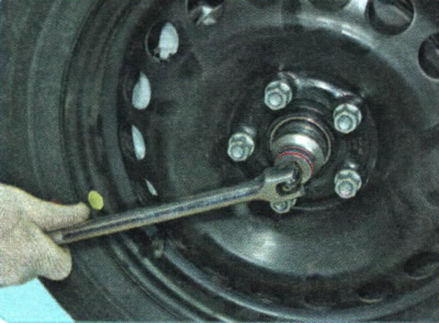
NOTE: If the vehicle is equipped with light alloy wheels, the center of the wheel hub blocks access to the hub nut. In this case, first remove the wheel and loosen the hub nut, holding the hub from turning with a tire iron, resting it on the two wheel fastening nuts screwed onto the hub studs.

NOTE: If the vehicle is equipped with light alloy wheels, the center of the wheel hub blocks access…


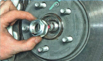
7. Completely unscrew the hub nut and remove the wheel.


NOTE: Be sure to replace the hub nut with a new one.

NOTE: Be sure to replace the hub nut with a new one.


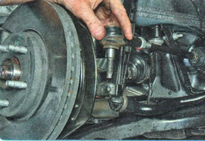
8. Disconnect the steering tie rod end from the steering knuckle (see "Replacing the outer tie rod end").
8. Disconnect the steering tie rod end from the steering knuckle (see «Replacing the outer tie rod…


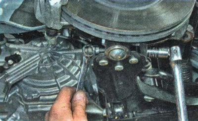
9. Loosen the nut of the tightening bolt securing the ball joint pin to the steering knuckle...
9. Loosen the nut of the tightening bolt securing the ball joint pin to the steering knuckle...


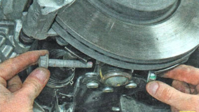
10. ...and remove the bolt.
10. ...and remove the bolt.


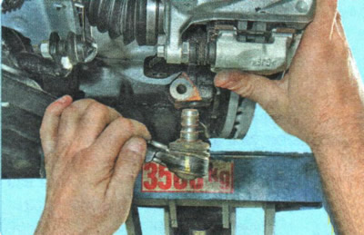
11. By pressing down the front suspension arm...
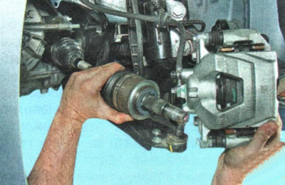


11. By pressing down the front suspension arm...


12. ... move the steering knuckle assembly with the shock absorber strut to the side and remove the splined tailpiece of the outer constant velocity joint of the front wheel drive from the hub.

HELPFUL TIP: If you cannot remove the joint tail by hand, knock it out of the hub with light hammer blows through a spacer made of soft metal or wood.
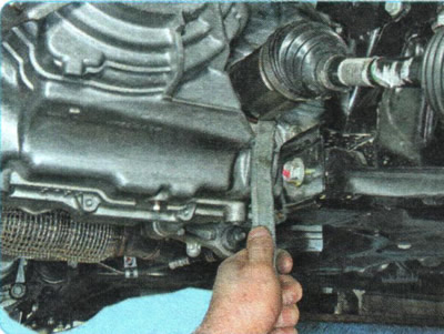

HELPFUL TIP: If you cannot remove the joint tail by hand, knock it out of the hub with light hammer…


13. Using a mounting blade, press out the inner drive joint tailstock from the differential axle gear...

NOTE: The gap between the inner joint housing and the gearbox housing is very small, so it is impossible to insert the end of the mounting blade into it completely at once. After inserting the pointed part of the mounting blade into the gap, carefully hammer the blade along the blade to drive its end deep into the gap, pushing the joint housing away from the housing with the blade like a wedge until the joint tailstock retaining ring comes out of the axle shaft gear. Then finally push the joint tailstock out of the gear with the blade.


CAUTION: When using a tire iron to press the inner joint out of the transmission axle gear, be careful not to damage the transmission case or joint.
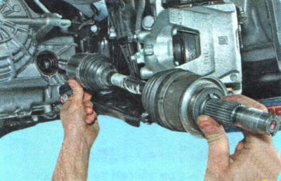

CAUTION: When using a tire iron to press the inner joint out of the transmission axle gear, be…


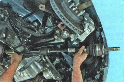
14. ...and remove the left front wheel drive assembly.
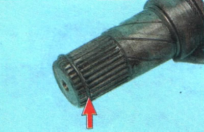
14. ...and remove the left front wheel drive assembly.


CAUTION: Replace the drive inner joint camshaft snap ring with a new one each time the drive is removed from the vehicle, otherwise the drive may accidentally come off the axle gear while driving.

CAUTION: Replace the drive inner joint camshaft snap ring with a new one each time the drive is…


15. Remove the right front wheel drive in the same way.


16. To install the drive, first insert the splined tail of the outer joint housing into the wheel hub and screw the hub nut until it stops, without tightening it completely.

17. Then insert the splined tailpiece of the inner joint housing into the axle shaft seal and turn the drive shaft slightly so that the splines of the joint tailpiece and the axle shaft gear align.

18. Move the front suspension arm down and, using a sharp movement of the shock absorber strut with the steering knuckle, press the drive into the axle shaft gear until the drive is secured with a retaining ring.

19. Attach the shock absorber strut ball joint to the lower arm.

20. Attach the steering rod to the steering knuckle.

21. Install the wheel and tighten the nuts until they stop, without tightening them completely.

22. After removing from the supports, place the car on the wheels and tighten the hub nut to a torque of 250 N·m.

23. Lock the hub nut by pressing the edge of its flange into the groove on the outer joint housing tailstock with a punch and hammer.

NOTE: The hub nut on a vehicle equipped with alloy wheels must be tightened and locked completely before installing the wheel, holding the hub from turning as you did when loosening it (see Note).


24. Tighten the wheel nuts (see "Wheel replacement").

25. Fill the manual gearbox with oil (see "Checking the level, topping up and replacing oil in a manual transmission") or working fluid in the automatic transmission (see "Checking the level, topping up and replacing the working fluid in the automatic transmission").

26. Install the mudguard and engine crankcase guard (see "Removal and installation mudguards and engine crankcase protection").

(The original article can be found on the resource «CHEVYMAN.ru»)

The article was checked: Vladimir Romannikov
This article is available at russian, bulgarian, belarusian, ukrainian, serbian, croatian, romanian, polish, slovak, hungarian

Share information:

Previous articles
Aveo T300: Front wheel drives
Next articles

Checking the technical condition of the front wheel drives
Possible faults of front wheel drives, their causes and methods of elimination
Design features of front wheel drives
Replacement of constant velocity joints


See similar articles on the topic of Chevrolet cars:
Front fender wheel opening molding Chevrolet Captiva 1 (2006-2018)
Possible faults of front wheel drives, their causes and methods of elimination Chevrolet Cruze 1 (2008-2016)
Removal the front wheel drives Chevrolet Lacetti 1 (2002-2009)
Removal the front wheel drives Chevrolet Lanos T150 (2002-2009)
Possible faults of the front wheel drive, their causes and methods of elimination Chevrolet Niva 1 (2002-2016)
Front wheel alignment angles Chevrolet Tahoe 1 (1992-2000)
Front Wheel Drives — General Information Chevrolet Orlando 1 (2010-2018)
Link in different formats to this page


Visitor comments

No comments yet


How much will 18 + 16 =


Aveo T300 (2012-2018) 
  • General information
  • Vehicle device
  • User manual
  • Main malfunctions
  • Maintenance
  • Power unit
  • Engine
  • Lubrication system
  • Cooling system
  • Supply system
  • Exhaust system
  • Transmission
  • Clutch
  • Manual gearbox
  • Automatic gearbox
  • Front wheel drives
  • Chassis
  • Front suspension
  • Rear suspension
  • Steering
  • Brake system
  • Body
  • Exterior
  • Interior
  • Doors and trunk
  • Security systems
  • Electrical equipment
  • Engine electrics
  • Equipment and devices
  • Heating and air conditioning
  • Electrical circuits


Aveo T250 (2006-2011) 
  • Manual
  • Driver's workplace
  • Salon equipment
  • Vehicle characteristics
  • Maintenance
  • Engine 1.5 SOHC
  • Engine repair
  • Fuel supply system
  • Control system
  • Cooling system
  • Engine 1.6 DOHC
  • Engine repair
  • Control system
  • Transmission
  • Clutch
  • Manual gearbox
  • Automatic gearbox
  • Wheel drive
  • Chassis
  • Wheel suspension
  • Steering
  • Brake system
  • Body
  • Exterior
  • Interior


Aveo T200 (2003-2008) 
  • General information
  • User manual
  • Power unit
  • Engine repair 1.5L SOHC
  • Fuel system
  • Control system
  • Cooling system
  • Transmission
  • Clutch
  • Manual gearbox
  • Automatic gearbox
  • Drive shafts
  • Chassis
  • Front suspension
  • Rear suspension
  • Steering
  • Brake system
  • Body
  • Exterior (external elements)
  • Interior (internal elements)
  • Electrical equipment
  • Equipment and devices
  • Electrical circuits


ChevyMan.ru © 2017-2026 · Mobile version · Feedback · Site search · Interesting to read · Sitemap: EN BG BY UA RS HR RO PL SK HU

Aveo 2003-2008 · Aveo 2006-2011 · Aveo 2012-2018 · Captiva 2006-2018 · Cruze 2008-2016 · Lacetti 2002-2009 · Lanos 2002-2009 · Niva 2002-2016 · Tahoe 1992-2000 · Tahoe 2000-2014 · Lumina 1 1989-1994 · Trailblazer 1 2001-2008 · Orlando 1 2010-2018 ·
🛡️ For your security and to improve our service, this site uses cookies. You can disable them in your browser.