
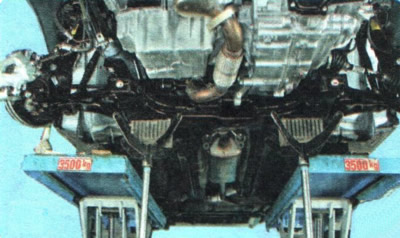
1. Place the vehicle on a lift or inspection pit.
2. Set the steering wheel to a position corresponding to the straight-ahead movement of the vehicle and fix it in this position.
HELPFUL TIP: To prevent damage to the airbag contact disc, secure the steering wheel from turning using the ignition locking mechanism. To do this, remove the key from the ignition and turn the steering wheel slightly until the shaft is secured by the anti-theft device.
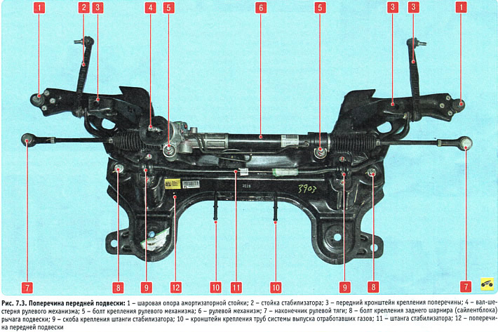
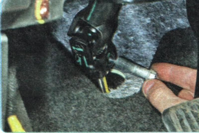
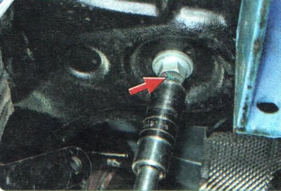
3. In the car's interior, under the instrument panel, unscrew the bolt of the terminal connection of the steering shaft with the pinion shaft 4 (figure 7.3) steering mechanism...
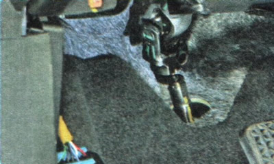
4. ...and separate the shafts.
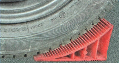
5. Place wheel chocks under the rear wheels, lift the front of the vehicle and remove the front wheels.
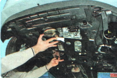
6. Remove the mudguards and engine crankcase protection (see "Removal and installation mudguards and engine crankcase protection").
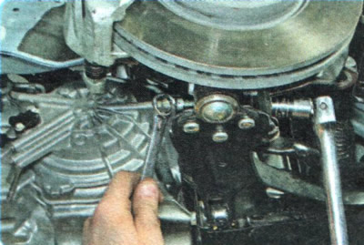
7. Disconnect the tips from both sides 7 (see figure 7.3) steering rods from the steering knuckle arms (see "Replacing the outer tie rod end").
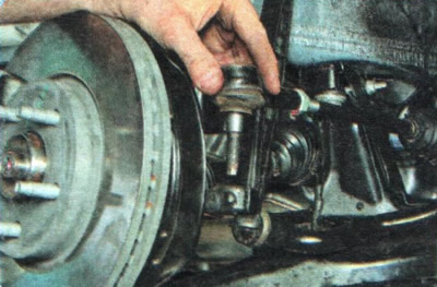
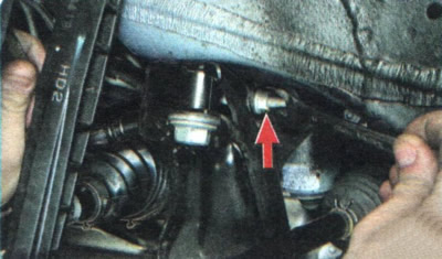
8. Loosen the nut of the clamping bolt of the terminal connection of the ball joint 1 to the steering knuckle.
9. Knock the bolt out of the hole...
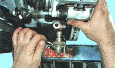
10. ...and press your finger out of your fist.
11. Similarly, disconnect the ball joint from the knuckle on the other side.
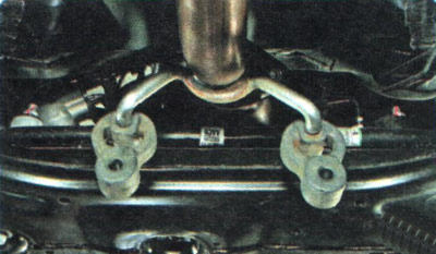
12. Remove the exhaust system suspension cushions from the brackets 10 on the crossmember.

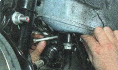
13. Unscrew the bolt securing the rear support of the powertrain suspension to the bracket on the gearbox and remove it from the holes.
14. Unscrew the bolt securing the support to the crossmember and remove the bolt from the holes in the crossmember and support.
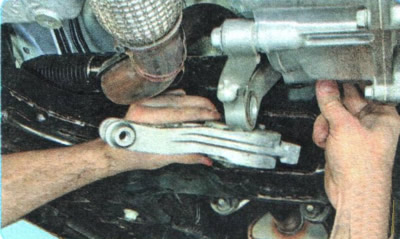
15. Remove the support.
16. Install supports under the front suspension crossmember (for example, hydraulic struts or a jack).
17. Unscrew one bolt on both sides securing the rear crossmember brackets to the body.
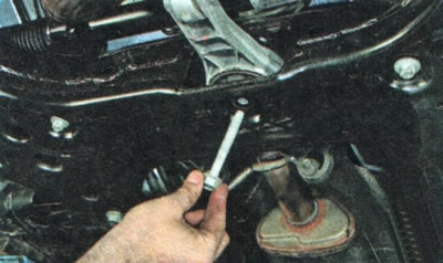
18. Loosen the nut of the electric vacuum pump bracket mounting bolt...
19. ...and remove the bolt from the holes.
20. Unscrew the front bracket mounting bolts on both sides 3 (see figure 7.3) crossbars to the body.
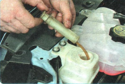
21. Pump out the working fluid from the power steering reservoir.
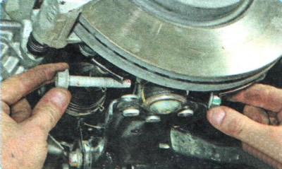
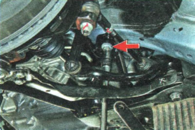
22. Unscrew the bolts securing the power steering tube holders to the suspension crossmember.
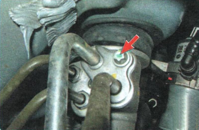
23. Unscrew the bolt securing the pressure plate of the tube flange to the power steering mechanism distribution valve block.
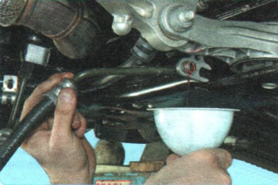
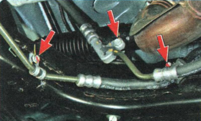
24. Disconnect the tubes from the valve block and drain the working fluid from them into a previously prepared container or plug them with plugs.
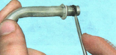
WARNING: The connection of the tubes to the steering gear is sealed with rubber rings. Replace the rings with new ones each time the connection is disconnected.
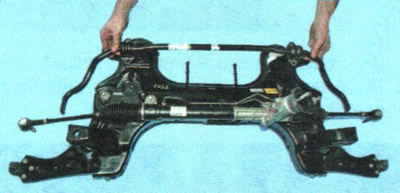
25. Remove the front suspension cross member assembly with the lower arms, steering gear and stabilizer bar by lowering it down.
26. If necessary, remove the stabilizer bar from the crossmember (see "Replacing the front suspension stabilizer bar components")...
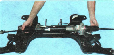
27. ...steering mechanism (see "Replacing the steering gear") and levers (see "Replacing the front suspension arm").
28. Install the crossmember in the reverse order of removal. Tighten the bolts to the torques specified in Appendix 1.
NOTE: When installing the steering gear, make sure that the rack is in the middle (neutral) position.
29. Bleed the power steering system (see "Bleeding the power steering system").
30. Check and, if necessary, adjust the wheel alignment angles (see "Checking and adjusting wheel alignment angles"). Use the services of workshops that have special equipment.
[For details, visit the website: ChevyMan.ru]