
Contents: Removal ↧ Installation ↧
Removal
1. Loosen the wheel nuts, lift the front of the car and securely fasten it to the stands. Block the rear wheels to prevent the vehicle from rolling off the stands. Remove the wheels.
2. If only one control arm is being removed, disconnect only that end of the stabilizer bar. If both levers are to be removed, disconnect both ends (see section 4).
3. Loosen the nut securing the ball joint pin to the steering knuckle and unscrew the tightening bolt (see illustration).
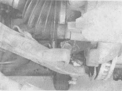
5.3. Before separating the lower arm of the front suspension from the steering knuckle, unscrew the nut of the pinch bolt (it is not visible in this illustration) and unscrew the tie bolt (indicated by the arrow)
4. Place a large pry bar or screwdriver between the front control arm and the steering knuckle, then lift the ball joint up and away from the steering knuckle (see illustration).
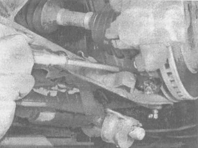
5.4. To separate the lower arm of the front suspension from the steering knuckle, press it with a pry bar or a large screwdriver
Caution: When removing the ball joint from the steering knuckle, be careful not to pull the inner constant velocity joint too far, otherwise it may be damaged.
5. Loosen the two bolts of the front suspension arm axle and remove the arm (see illustrations).
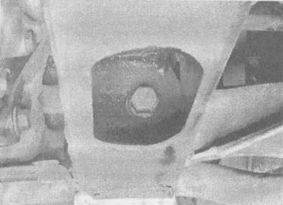
5.5a. To separate the lower arm of the front suspension from the subframe, unscrew the lower arm nut (it is not shown here) and remove the bolt (indicated by the arrow)... |
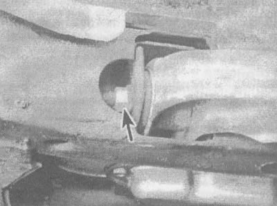
5.5b....and the axle nut (indicated by the arrow) and remove the bolt (this illustration shows a portion of the bolt with threads) |
6. The front suspension arm bushings are replaceable, but replacing them requires special tools and experience. Carefully inspect the bushings for hardening, wear and cracks. If there are signs of wear or aging, take the lever to a service or repair shop.
Installation
7. Position the suspension arm in the suspension support and insert the axle bolts. Do not tighten the bolts yet.
8. Insert the ball joint pin into the steering knuckle, insert a new pinch bolt and nut, and tighten the nut to the torque specified in the specifications in this chapter.
9. Place a trolley jack under the ball joint and raise the jack until the vehicle is raised off the stand. Tighten the control arm axle bolts to the torque specified in the specifications in this chapter.
10. Connect the anti-roll bar (see section 4).
11. Install the wheel and lower the vehicle. Tighten the wheel nuts to the torque specified in chapter 1.
12. Take the vehicle to a service or wheel alignment shop to check the front wheel alignment and adjust if necessary.
(The article is based on data from the website «ChevyMan»)