


The rear suspension features an axle beam with coil springs, to which the longitudinal arms and transverse reaction rod are connected (see illustration). Vibration damping is achieved by vertically mounted shock absorbers located between the axle and the chassis.
The rack and pinion steering mechanism is located behind the engine and drives the steering rods, which connect to the steering knuckles. Usually (standard) there is hydraulic power steering and the steering column is designed to fold in the event of a collision.
Note: Vehicles use both imperial and metric systems for various suspension and steering components, so you will need to have both types of tools available before you begin.
Often when working with suspension and steering components, you may come across fasteners that seem impossible to remove. These parts are located underneath the vehicle and are constantly exposed to water, road dirt, rust or freeze, making their removal extremely difficult. To loosen these parts without damaging them, you should use a large amount of penetrating oil, giving it some time to soak in. Using a stiff brush to clean the threads will also help make it easier to loosen bolts and nuts and prevent damage to the threads. Sometimes a sharp blow with a hammer and punch will help break the connection between the threads of nuts and bolts, but care must be taken to ensure that the punch does not slip off the fastener and strip the threads. Sometimes heating the "stuck" fasteners and surrounding areas also helps, but this is not recommended because it poses a fire hazard. You can use auxiliary guides or rods or tubes to increase the shoulder, but never use the ratchet mechanism (ratchet) as it can be damaged. Sometimes when loosening a nut or bolt it makes sense to first tighten it before loosening it. If drastic measures had to be taken to unscrew, such fasteners should be replaced with new ones during installation.
Since most of the operations described in this chapter involve working underneath the vehicle, a lift is required. It is preferable to use a stationary hydraulic lift, which can also be used to support certain parts during various operations.
Warning: Never rely solely on the jack or work under the vehicle when it is supported solely by the jack. Whenever any suspension or steering components are loosened or removed, they must be inspected and, if necessary, replaced with new parts of similar quality and design. It is necessary to strictly follow the technical specifications for tightening torques of threaded connections in order to correctly assemble and fasten. Never attempt to heat or straighten any suspension or steering components. Replace any warped or damaged parts with new ones.
Note: Before performing any operation that requires disconnecting the battery on vehicles equipped with the Delco Loc II audio system, be sure to disable the Delco Loc II audio system lock.
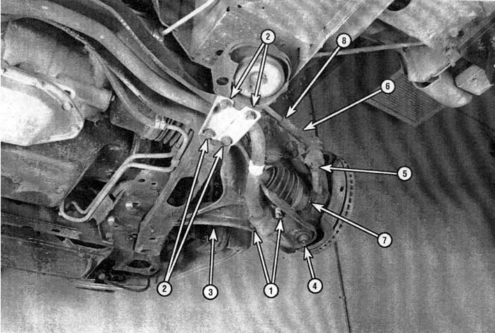
1.1a. Front suspension parts: 1 - anti-roll bar bush clamp fastening nuts, 2 - anti-roll bar reinforcement nuts, 3 - lower arm, 4 - ball joint, 5 - outer tie rod ball joint pin nut, 6 - outer tie rod, 7 - steering knuckle, 8 - outer tie rod pin nut
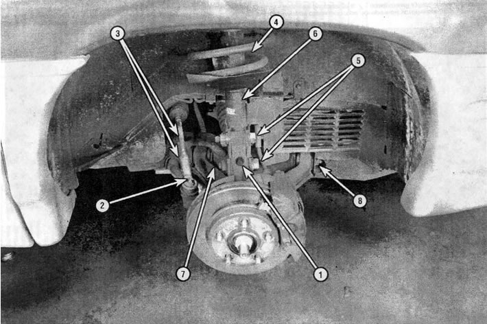
1.1b. Front suspension parts: 1 - steering knuckle, 2 - outer tie rod, 3 - outer tie rod pin nut, 4 - coil spring, 5 - steering knuckle to strut mounting bolts and nuts, 6 - strut assembly, 7 - lower arm, 8 - lower arm axle bolts and nuts
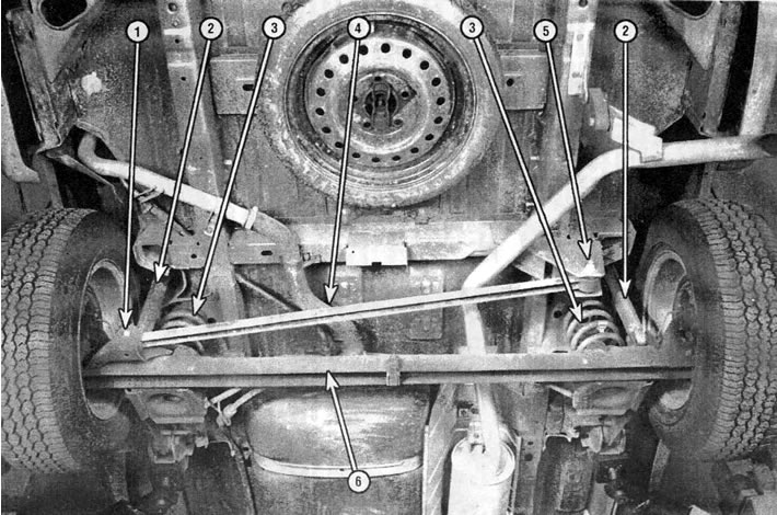
1.2. Rear suspension parts: 1 - lower bolt of the transverse reaction rod attachment to the axle beam, 2 - shock absorber, 3 - cylindrical coil spring, 4 - transverse reaction rod, 5 - upper bolt of the transverse reaction rod attachment bracket to the body, 6 - axle beam
Original version of the article on the website: «ChevyMan.ru»