ChevyMan.ru
Mazda Mitsubishi Toyota Land Rover Honda Kia Nissan
English Русский
Български
Беларускі
Український
Српски
Hrvatski
Română
Polski
Slovenský
Magyar
|
Articles | Sitemap | Contacts |


Home   Aveo   Captiva   Cruze   Lacetti   Lanos   Niva   Tahoe   Others  
Orlando 1 (2010-2018) Trailblazer 1 (2001-2008, petrol) Lumina 1 (1989-1994)
  • Home
  • Chevrolet
  • Lumina 1
  • Chassis
  • Car suspension
  • Removal, checking and installation rear shock absorbers

Removal, checking and installation rear shock absorbers (Chevrolet Lumina 1)

            0

Contents: Removal ↧ Examination ↧ Installation ↧

Removal


1. Loosen the rear wheel nuts, raise the rear of the vehicle and securely support it on struts.

2. Support the rear axle with a jack (see illustration) and remove the rear wheels.
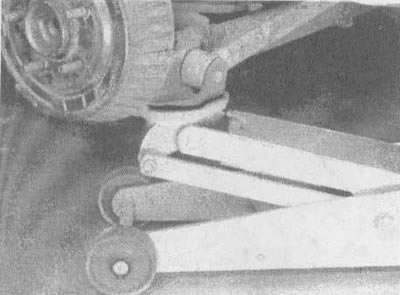
9.2. Before removing the shock absorber, place a trolley jack under the rear axle; otherwise, when…

9.2. Before removing the shock absorber, place a trolley jack under the rear axle; otherwise, when you disconnect the lower shock absorber mounting bolt, the axle, under spring pressure, may drop sharply and cause injury


3. If the vehicle is equipped with an electronic level control system, the air lines must be disconnected before removing the shock absorber. Air lines use spring clamp connectors with integral seals in the retainer and double O-ring seals at the end of the air line. Before disconnecting the connector, clean it thoroughly, then compress the spring clip (see illustration) and separate the pipe from the shock absorber (the left shock absorber has an inlet line and a bypass pipe; the right shock absorber only has a bypass pipe).
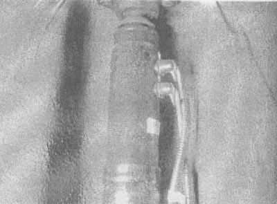
9.3. On vehicles equipped with a body position adjustment system, the left shock absorber (shown in…

9.3. On vehicles equipped with a body position adjustment system, the left shock absorber (shown in the illustration) connects to the compressor and the right shock absorber (the right shock absorber has only one connection for the bypass pipe). To separate the air line, simply squeeze the spring clip and pull the connector out; to reconnect the line, lubricate the O-rings, then push the connector all the way into the fitting until it snaps into place


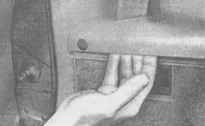
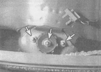
4. Unscrew the upper shock absorber mounting nuts (see illustrations).
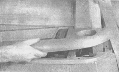
9.4a. To get to the upper shock absorber nuts, remove this decorative strip by hand,...

9.4a. To get to the upper shock absorber nuts, remove this decorative strip by hand,...
9.4b....unhook each of the buttons,...

9.4b....unhook each of the buttons,...

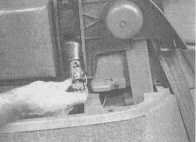
9.4v.... lift the decorative strip up and disconnect the electrical connector of the lamp that…

9.4v.... lift the decorative strip up and disconnect the electrical connector of the lamp that turns on when the door is opened
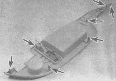
9.4g. This is what the removed decorative strip looks like from the back side. All snap-on…

9.4g. This is what the removed decorative strip looks like from the back side. All snap-on fasteners are shown here


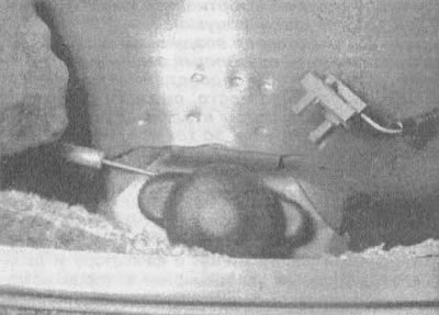
9.4d. Press this rubber protective cap off the top of the shock absorber...

9.4d. Press this rubber protective cap off the top of the shock absorber...
9.4e....and unscrew these three nuts (indicated by arrows)

9.4e....and unscrew these three nuts (indicated by arrows)

5. Unscrew the nuts and bolts of the lower shock absorber mount (see illustration).
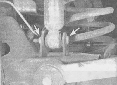
9.5. Lower nut and bolt for fastening the shock absorber (indicated by arrows)

9.5. Lower nut and bolt for fastening the shock absorber (indicated by arrows)


6. Remove the shock absorbers.


Examination


7. Holding each shock absorber vertically, stretch and compress it. The movement should be smooth and there should be no jamming. Check for fluid leaks. If the shock absorber is leaking, replace it, do the same if it feels stuck when compressed. Always replace shock absorbers in pairs.

Installation


8. Place each shock absorber back in place and insert the bolts. Tighten the upper nuts to the torque specified in the specifications in this chapter. Lower the vehicle and tighten the lower bolts to the torque specified in the specifications in this chapter.

9. If the vehicle is equipped with an electronic level control system, connect the air lines. Lubricate the o-rings and install the air lines and connectors along the entire length of the pipe. After pressurizing the system to 100 psi, check for leaks using a soapy water solution.

The article was checked: Vladimir Romannikov
This article is available at russian, bulgarian, belarusian, ukrainian, serbian, croatian, romanian, polish, slovak, hungarian

Share information:

Previous articles
Lumina 1: Car suspension
Next articles

Checking and replacing the ball joint
Removal and installation the hub and steering knuckle
Removal and installation the front hub and wheel bearings
Removal and installation front suspension arms
Removal and installation the front anti-roll bar and its bushings
Removal and installation the transverse jet rod
Removal, checking and installation rear suspension springs
Removal and installation the rear hub
Removal and installation the rear axle
General information about the electronic level control system


See similar articles on the topic of Chevrolet cars:
Checking the technical condition of the rear suspension parts on the car Chevrolet Aveo T300 (2012-2018)
Cleaning and checking the rear output drive housing Chevrolet Captiva 1 (2006-2018)
Replacing the rear shock absorber Chevrolet Cruze 1 (2008-2016)
Checking the condition of wheels and tires Chevrolet Lacetti 1 (2002-2009)
Rear view mirrors Chevrolet Lanos T150 (2002-2009)
Checking shock absorbers on a stand Chevrolet Niva 1 (2002-2016)
Rear shock absorbers — removal and installation Chevrolet Tahoe 1 (1992-2000)
Link in different formats to this page


Visitor comments

No comments yet


How much will 26 + 49 =


Orlando 1 (2010-2018) 
  • General information
  • Introduction to manual
  • User manual
  • Maintenance
  • Troubleshooting
  • Power unit
  • Engine repair
  • Fuel and control system
  • Cooling and lubrication system
  • Ignition system
  • Transmission
  • Clutch
  • Gearbox
  • Drive shafts
  • Chassis
  • Car suspension
  • Steering
  • Brake system
  • Body
  • Exterior (external elements)
  • Doors, locks and windows
  • Electrical equipment
  • Equipment and devices
  • Windscreen wipers
  • Power devices
  • Electrical diagrams


Trailblazer 1 (2001-2008) 
  • General information
  • User manual
  • Troubleshooting
  • Maintenance
  • Power unit
  • Engine in a car
  • Engine overhaul
  • Cooling and heating
  • Fuel and exhaust system
  • Engine electrical equipment
  • Engine control
  • Transmission
  • Automatic gearbox
  • Transfer case
  • Drive shafts and cardan
  • Chassis
  • Brake system
  • Car suspension
  • Steering
  • Body
  • Exterior (external elements)
  • Interior (internal elements)
  • Doors, locks and windows
  • Electrical equipment
  • Equipment and devices
  • Electrical circuits


Lumina 1 (1989-1994) 
  • General information
  • Maintenance
  • Power unit
  • Engine 3.1L V6
  • Engine 3.8L V6
  • Engine overhaul
  • Cooling system
  • Power and exhaust system
  • Fuel injection
  • Engine electrical equipment
  • Reduced exhaust gas toxicity
  • Transmission
  • Automatic gearbox
  • Drive shafts
  • Chassis
  • Brake system
  • Car suspension
  • Steering
  • Body
  • Heating and air conditioning
  • Repair of body elements
  • Doors, covers and windows
  • Interior (internal elements)
  • Electrical equipment
  • Equipment and devices
  • Electrical circuits


ChevyMan.ru © 2017-2026 · Mobile version · Feedback · Site search · Interesting to read · Sitemap: EN BG BY UA RS HR RO PL SK HU

Aveo 2003-2008 · Aveo 2006-2011 · Aveo 2012-2018 · Captiva 2006-2018 · Cruze 2008-2016 · Lacetti 2002-2009 · Lanos 2002-2009 · Niva 2002-2016 · Tahoe 1992-2000 · Tahoe 2000-2014 · Lumina 1 1989-1994 · Trailblazer 1 2001-2008 · Orlando 1 2010-2018 ·
🛡️ For your security and to improve our service, this site uses cookies. You can disable them in your browser.