
2. Support the axle in the middle with a jack stand.
3. If the vehicle is equipped with an electronic level control system, disconnect the height sensor rod from the ball stud (see illustrations).
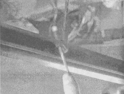
13.3a. On vehicles equipped with an electronic level control system, it is necessary to disconnect the height sensor rod from the ball joint on the axle. First, use a small screwdriver to press down on the retaining spring clip,... |
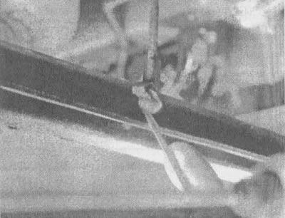
13.3b....then remove the tie rod end from the ball joint |
4. Disconnect the rear parking brake cables from the front cable at the connectors, remove the brackets and remove the cable fixing clamps from the brackets on the trailing arms of the suspension (see chapter 9, section 11). Feed the rear cables through the holes in the trailing arms until they clear the axle. Disconnect the lines from the brake hoses (see chapter 9, section 8).
5. Disconnect the lower ends of the shock absorbers (see section 9) and transverse jet thrust (see section 10). Hang the lower end of the transverse reaction rod on the wire.
6. Carefully lower the axle until the springs are released, then remove the springs and spacers.
7. Support the front ends of the trailing arms with struts and remove the nuts and bolts (see illustration).
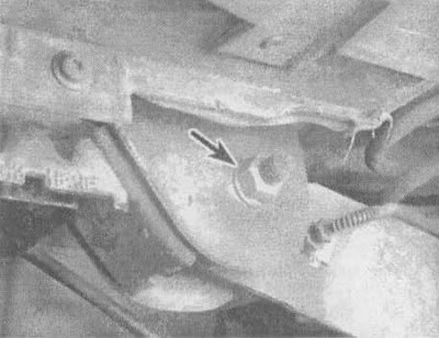
13.7. To separate the trailing arm from the frame, unscrew the nut (indicated by the arrow) and remove the bolt from each side of the trailing arm (the photo shows the left trailing arm, the other side is similar)
8. Remove the axle.
9. Check the lever bushings. If they are cracked or dry, replace them.
10. Installation is carried out in reverse order. Be sure to tighten the trailing arm bushing bolt nuts to the torque specified in technical conditions of this chapter.
11. After completing the work, bleed the brakes (see chapter 9, section 9).