


Record the working diagrams according to the instructions supplied with the stand, after completing at least 5 working cycles, at a shock absorber working fluid temperature of (20+5)°C, a flywheel speed of 60 min and a rod stroke length of 100 mm for the front shock absorber.
Curve diagram (figure 4-16) should be smooth, and at the transition points (from recoil stroke to compression stroke) - without sections parallel to the zero line.
Evaluation of results according to the diagram. The resistance of the recoil and compression strokes is determined by the largest ordinates of the corresponding diagrams.
The highest point of the recoil curve at a scale of 1 mm = 47 N (4.8 kgf) should be located from the zero line at a distance A equal to: 33.3-40.7 mm for the front shock absorbers, 23.5-30.5 mm for the rear.
The highest point of the compression stroke curve with the same scale should be located from the zero line at a distance B equal to 3.5-6.5 mm - for front and rear shock absorbers.
The control values of the ordinates on the diagrams of the front and rear shock absorbers are specified for cold shock absorbers at a shock absorber fluid temperature of (20+5)°C.
Speed characteristic of the shock absorber (see figure 4-15) at a shock absorber fluid temperature of (20±5)°C and a piston rod stroke of (100±1) mm, it should fit into zone 1 during rebound and into zone 2 during compression. Force control Fotb, Fotb1, Foh, Fszh1 produce according to TU 37.370.016-2001.
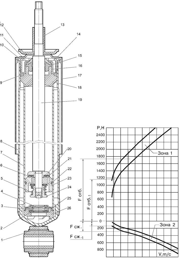
Figure 4-16. Shock absorber operating diagram:
I - recoil force;
II - force during compression stroke.
(The article was reprinted from the website ChevyMan.ru)