


Remove the rear wheel caps (if available) and loosen the rear wheel nuts.
Place the gear shift lever in neutral position.
Raise the vehicle, loosen the rear wheel nuts and remove the rear wheels.
Disconnect the rear parking brake cable from the front cable.
Unscrew and remove the nuts with washers, remove the brackets securing the rear cable to the body floor.
Remove the front parking brake cable release spring.
Disconnect the lock nut and adjusting nut of the front parking brake cable, remove the spacer sleeve and cable guide.
Disconnect the brake pipe from the brake hose, plug the brake pipe, remove the bracket and disconnect the brake hose from the body bracket.
Loosen the nut of the bolt securing the rear brake pressure regulator drive lever stand to the axle beam, remove the bolt, disconnect the stand and remove the stand bushings from the rear axle bracket.
Loosen the nuts of the bolts securing the propeller shaft flange to the rear axle gearbox flange and remove the bolts, disconnect the propeller shaft flange from the rear axle gearbox flange.
Loosen the nuts of the shock absorber mounting bolts 13 (see figure 4-12) to the rear axle beam.
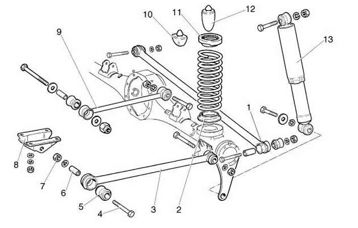
Figure 4-12. Rear suspension parts:
1 - crossbar;
2 - lower spring cup;
3 - lower longitudinal bar;
4 - lower rod mounting bolt;
5 - rubber bushing of the hinge;
6 - spacer sleeve;
7 - nut;
8 - bracket;
9 - upper longitudinal bar;
10 - additional compression stroke buffer;
11 - Upper spring gasket;
12 - compression stroke buffer;
13 - rear shock absorber.
Place stands under the rear axle beam, lower the car until the shock absorbers are unloaded, and remove the shock absorber mounting bolts.
Loosen the nuts of the bolts securing the transverse 1 and longitudinal 3 rods of the rear suspension to the rear axle beam, remove the bolts, lift the car, remove the rear suspension springs and remove the rear axle assembly. Perform the work by two performers.
Unscrew the tee mounting nut from the rear axle beam, disconnect the brake pipes from the brake cylinders and from the rear axle beam, install technological plugs on the pipes, remove the pipeline assembly with the flexible hose.
The installation of the rear suspension is carried out in the reverse order of removal, but do not perform the final tightening of the nuts of the shock absorber mounting bolts and rear suspension rods.
Tightening torque:
- wheel fastening nuts — 85...95 Nm (8.5...9.5 kgf·m).
Place the car on a lift, use your hands to press the rear suspension 2-3 times, applying a load of 400...500 N (6.5...7.5 kgf) to the rear bumper, finally tighten the nuts of the shock absorber mounting bolts and rear suspension rods.
Tightening torque:
- nuts of shock absorber mounting bolts — 40...60 Nm (4.0...6.0 kgf·m);
- nuts for fastening bolts of cross and longitudinal rods — 70...80 Nm (7.0...8.0 kgf·m).
Check the oil level in the rear axle housing and top it up if necessary. The oil level should be up to the lower edge of the filler hole.
Bleed the brake system following the recommendations in the subsection "Removal air from the hydraulic drive".
Adjust the parking brake following the recommendations in the subsection "Adjusting the parking brake".
Check the efficiency of the rear brakes in accordance with the requirements of TI 3100.25100.13062.
In this case, install springs of the same class on the suspension as on the front suspension. In exceptional cases, if the front suspension has class "A" springs, and there are no such springs for the rear suspension, it is permissible to install class "B" springs. If class "B" springs are installed in the front suspension, then only class "B" springs are installed in the rear suspension.
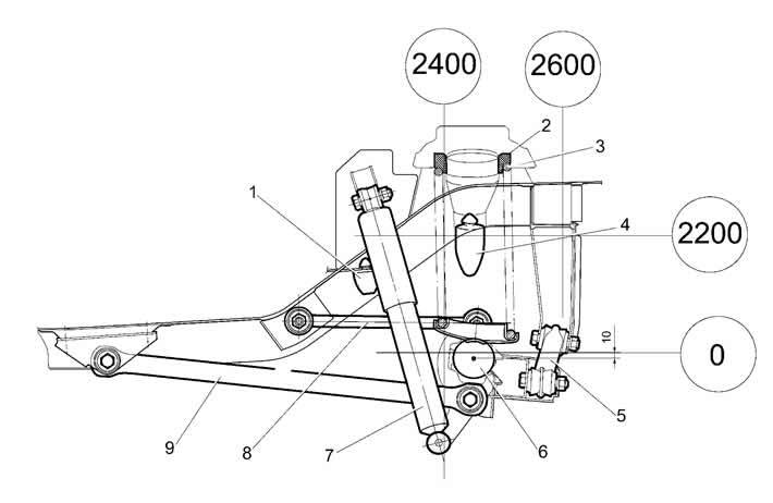
Figure 4-13. Rear suspension installation diagram:
1 - additional compression buffer;
2 - upper spring gasket;
3 - spring;
4 - compression stroke buffer;
5 - crossbar;
6 - rear axle beam;
7 - rear shock absorber;
8 - upper longitudinal bar;
9 - lower longitudinal bar.
[The original text can be found on the website «ChevyMan.ru»]