
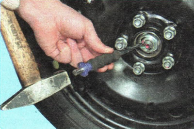
1. Remove the decorative cap and loosen the hub nut.
2. Loosen the hub nut and wheel nuts.
3. Raise and support the front of the vehicle. Remove the wheel.
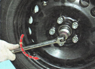
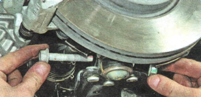
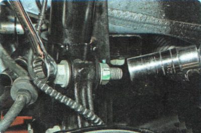
NOTE: If the vehicle is equipped with light alloy wheels, the center of the wheel hub blocks access to the hub nut. In this case, first remove the wheel and loosen the hub nut, holding the hub from turning with a tire iron, resting it on the two wheel fastening nuts screwed onto the hub studs.
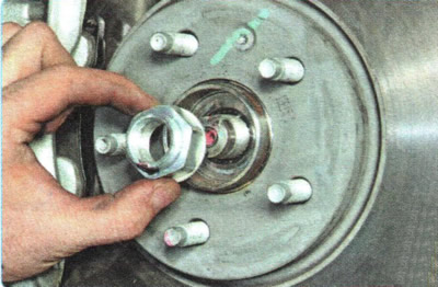
4. Completely unscrew the hub nut.
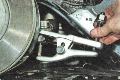
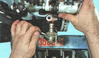
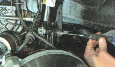
5. Loosen the outer tie rod end joint pin mounting nut. Install the ball joint puller...
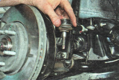
6. ...and press the pin out of the steering knuckle arm.
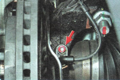
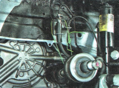
7. Unscrew the mounting bolt...
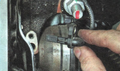
8. ...and remove the wheel speed sensor from the hole in the steering knuckle.
9. Loosen the nut of the clamping bolt of the terminal connection of the ball joint to the steering knuckle...
10. ...and remove the bolt from the hole.
11. Press your finger out of your fist.
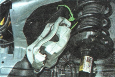
12. Remove the front wheel brake caliper assembly (see "Replacing the front wheel brake caliper"), without disconnecting the brake hose, and secure it with wire, preventing the hose from twisting or being pulled.
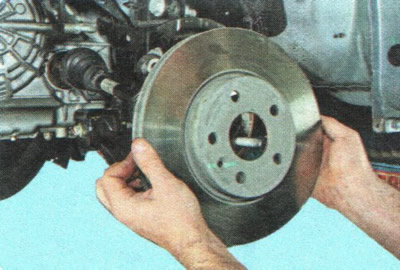
13. Remove the brake disc (see "Replacing the brake disc").
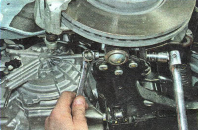
14. Loosen the nuts of the bolts securing the steering knuckle to the shock absorber strut...
15. ...and knock the bolts out of the holes.
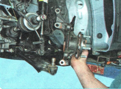
16. While holding the front wheel drive shaft from dropping sharply, remove the steering knuckle from the outer drive joint tailstock.
USEFUL TIP: If it is difficult to remove the outer joint tail from the front hub, carefully, without damaging the threads, knock it out of the hub with a hammer through a drift or a wooden block of a suitable size.
17. To protect the inner joint of the drive shaft from damage, hang the shaft on a wire.
18. Install the knuckle in the reverse order of removal. Tighten the threaded connections to the torque specified in Appendix 1.
WARNINGS: When installing the wheel speed sensor, carefully align the hole in its housing with the threaded hole in the knuckle. Do not rotate the sensor around the longitudinal axis during installation.
The increase in resistance to the sensor movement should be felt only in the last 2 mm before it is fully seated in the knuckle. If the sensor enters the knuckle hole with great resistance from the very beginning of installation, remove the sensor and eliminate the cause of jamming (dirt, burrs on the body, etc.). It is strictly forbidden to press the sensor in with a hammer.
19. Press the brake pedal all the way down several times. This is necessary to eliminate the gaps in the brake mechanisms that appeared after their removal.
20. Check and, if necessary, adjust the wheel alignment angles (see "Checking and adjusting the wheel alignment angles", p. 175). Use the services of workshops with special equipment.
[The original text can be found on the website «chevyman.ru»]