ChevyMan.ru
Mazda Mitsubishi Toyota Land Rover Honda Kia Nissan
English Русский
Български
Беларускі
Український
Српски
Hrvatski
Română
Polski
Slovenský
Magyar
|
Articles | Sitemap | Contacts |


Home   Aveo   Captiva   Cruze   Lacetti   Lanos   Niva   Tahoe   Others  
Cruze 1 (2008-2016)
  • Home
  • Cruze
  • J300 (2008-2016)
  • Chassis
  • Front suspension
  • Removal and installation the front suspension steering knuckle

Removal and installation the front suspension steering knuckle (Chevrolet Cruze J300)

            0

You will need: keys "8", "15", "18", "32", TORX T30, a flat-blade screwdriver, a hammer, a punch, a ball joint puller.

You will need: keys «8», «15», «18», «32», TORX T30, a flat-blade screwdriver, a hammer, a punch, a…


1. Loosen the wheel nut.
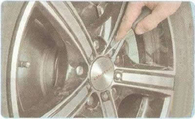
1. Loosen the wheel nut.


2. Using a screwdriver, remove the plug...
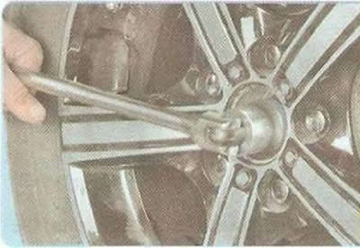
2. Using a screwdriver, remove the plug...


3. ...and loosen the hub nut.

4. Raise and support the front of the vehicle.

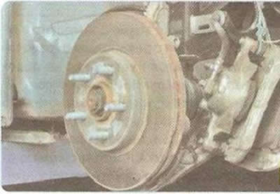
5. Remove the wheel.
5. Remove the wheel.


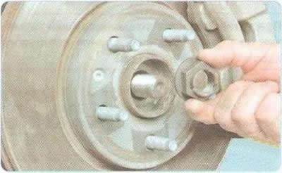
6. Completely unscrew the hub nut and remove it.


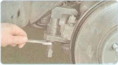
7. Remove the bolts securing the caliper to the steering knuckle.
7. Remove the bolts securing the caliper to the steering knuckle.


8. Remove the caliper assembly without disconnecting the brake hose and secure it with wire, preventing the hose from twisting or being pulled.
8. Remove the caliper assembly without disconnecting the brake hose and secure it with wire,…


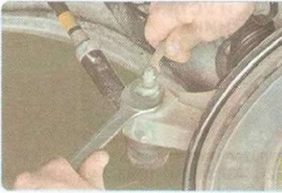
9. Loosen the nut securing the outer tie rod end hinge pin, holding the pin from turning.
9. Loosen the nut securing the outer tie rod end hinge pin, holding the pin from turning.


10. Install the ball joint puller and press the pin out of the steering knuckle boss (see "Replacing the outer tie rod end").


10. Install the ball joint puller and press the pin out of the steering knuckle boss (see…


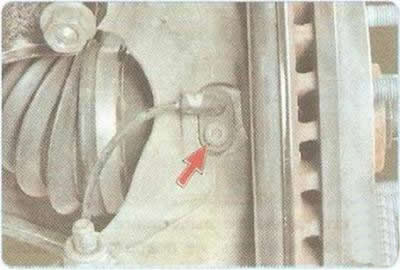
11. Remove the fastening screw...

11. Remove the fastening screw...


12. ...and remove the wheel speed sensor from the hole in the steering knuckle.
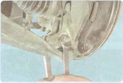
12. ...and remove the wheel speed sensor from the hole in the steering knuckle.


13. Loosen the nut of the clamping bolt of the terminal connection of the steering knuckle with the ball joint, remove the bolt and remove the ball joint pin from the steering knuckle.
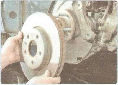
13. Loosen the nut of the clamping bolt of the terminal connection of the steering knuckle with the…


14. Remove the brake disc (see "Replacing the brake disc of the front wheel brake mechanism").


15. Push out of the hub (towards the gearbox), as far as possible, the splined tailpiece of the outer constant velocity joint (CV joint) of the front wheel drive.
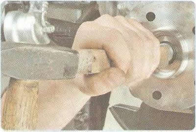
15. Push out of the hub (towards the gearbox), as far as possible, the splined tailpiece of the…


If it is difficult to remove the outer joint tailpiece without damaging the threads, knock it out of the hub with a hammer through a drift or a wooden block of a suitable size.


16. Holding the drive shaft from dropping sharply, remove the steering knuckle assembly with the hub.

17. Hang the drive shaft on the wire.
17. Hang the drive shaft on the wire.


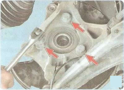
18. Remove the three bolts securing the hub to the steering knuckle.
18. Remove the three bolts securing the hub to the steering knuckle.


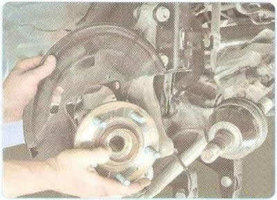
19. Remove the hub.


19. Remove the hub.


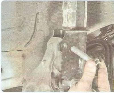
20. Loosen the nuts of the bolts securing the steering knuckle to the shock absorber strut and remove the bolts.
20. Loosen the nuts of the bolts securing the steering knuckle to the shock absorber strut and…


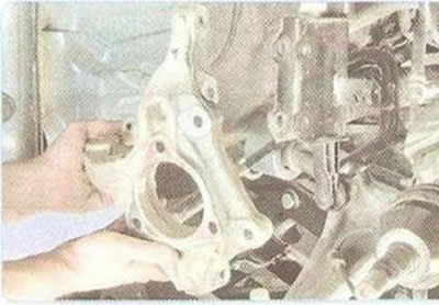
21. Remove the steering knuckle.

22. Install the parts in the reverse order of removal. Tighten the bolts and nuts to the torque specified in Appendix 1.

Caution: When installing, apply anaerobic sealant to the threads of the drive shaft splined end retaining nut.


23. Press the brake pedal all the way down several times. This is necessary to eliminate the gaps in the brake mechanisms that appeared after their removal.

24. Install the wheel speed sensor in the reverse order of removal. If the anti-lock brake system malfunction indicator lamp does not go out after installing the wheel speed sensor, contact a service station for ABS diagnostics.

Warning: When installing the sensor, precisely align the hole in its housing with the threaded hole in the knuckle. Do not rotate the sensor around the longitudinal axis during installation. An increase in resistance to the sensor movement should be felt only in the last 2 mm before it is fully seated in the knuckle. If the sensor enters the knuckle hole with great resistance from the very beginning of installation, remove the sensor and eliminate the cause of jamming (dirt, burrs on the body, etc.). It is strictly forbidden to press in the wheel speed sensor with a hammer.

The article was checked: Vladimir Romannikov
This article is available at russian, bulgarian, belarusian, ukrainian, serbian, croatian, romanian, polish, slovak, hungarian

Share information:

Previous articles
Cruze 1: Front suspension
Next articles

Replacing the front suspension stabilizer bar
Replacing the front suspension arm
Replacing the front suspension ball joint
Replacing the upper support of the front suspension shock absorber strut
Removal and installation the front suspension subframe
Checking and adjusting wheel alignment angles


See similar articles on the topic of Chevrolet cars:
Removal and installation the front suspension steering knuckle Chevrolet Aveo T300 (2012-2018)
Steering knuckle, front wheel hub Chevrolet Captiva 1 (2006-2018)
Front suspension device Chevrolet Lacetti 1 (2002-2009)
Replacing the silent block and cushion of the front suspension arm Chevrolet Lanos T150 (2002-2009)
Front suspension device Chevrolet Niva 1 (2002-2016)
Front suspension knuckle Chevrolet Tahoe 2 and 3 (2000-2014)
Suspension and steering check (every 3000 miles or 3 months) Chevrolet Lumina 1 (1989-1994)
Link in different formats to this page


Visitor comments

No comments yet


How much will 14 + 17 =


Cruze 1 (2008-2016) 
  • General information
  • User manual
  • Troubleshooting
  • Maintenance
  • Power unit
  • Engine repair
  • Lubrication system
  • Cooling system
  • Exhaust system
  • Supply system
  • Control system
  • Transmission
  • Clutch
  • Car gearbox
  • Front wheel drives
  • Chassis
  • Front suspension
  • Rear suspension
  • Steering
  • Brake system
  • Body
  • Exterior (external elements)
  • Interior (internal elements)
  • Doors, covers and windows
  • Heating and air conditioning
  • Security systems
  • Electrical equipment
  • Equipment and devices
  • Power devices
  • Lighting and signaling
  • Electrical circuits


ChevyMan.ru © 2017-2026 · Mobile version · Feedback · Site search · Interesting to read · Sitemap: EN BG BY UA RS HR RO PL SK HU

Aveo 2003-2008 · Aveo 2006-2011 · Aveo 2012-2018 · Captiva 2006-2018 · Cruze 2008-2016 · Lacetti 2002-2009 · Lanos 2002-2009 · Niva 2002-2016 · Tahoe 1992-2000 · Tahoe 2000-2014 · Lumina 1 1989-1994 · Trailblazer 1 2001-2008 · Orlando 1 2010-2018 ·
🛡️ For your security and to improve our service, this site uses cookies. You can disable them in your browser.