ChevyMan.ru
Mazda Mitsubishi Toyota Land Rover Honda Kia Nissan
English Русский
Български
Беларускі
Український
Српски
Hrvatski
Română
Polski
Slovenský
Magyar
|
Articles | Sitemap | Contacts |


Home   Aveo   Captiva   Cruze   Lacetti   Lanos   Niva   Tahoe   Others  
Cruze 1 (2008-2016)
  • Home
  • Cruze
  • J300 (2008-2016)
  • Chassis
  • Front suspension
  • Removal and installation the front suspension subframe

Removal and installation the front suspension subframe (Chevrolet Cruze J300)

            0

1. Disconnect the wire from the negative terminal of the battery.

1. Disconnect the wire from the negative terminal of the battery.


2. Set the steering wheel to the straight-ahead position.
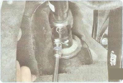
2. Set the steering wheel to the straight-ahead position.


3. In the passenger compartment, under the pedal assembly, unscrew the clamp bolt of the terminal connection of the lower cardan joint of the intermediate shaft with the steering gear shaft (see "Removal and installation the steering column").

Helpful Hint: When removing the steering column, mark in any way possible the relative positions of the terminal connection of the lower cardan joint of the intermediate shaft and the steering gear shaft.


In addition, the splines of the steering gear shaft and the splines of the lower universal joint have chamfers that must be aligned during installation.


4. Place the vehicle on a lift.

5. If you are working on a viewing ditch, apply the parking brake to the vehicle and install the anti-rollback stops ("shoes") under the rear wheels. Lift both sides of the front of the vehicle and place it on secure supports.

6. Remove both front wheels.

6. Remove both front wheels.


7. Remove the engine splash guards (see "Removal and installation engine mudguards").

8. Remove the lower cover of the front bumper trim (see "Removal and installation the front bumper").
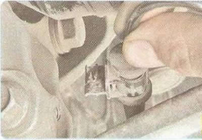
8. Remove the lower cover of the front bumper trim (see «Removal and installation the front…


9. Disconnect the wheel speed sensor wire harness clamps from the steering knuckles.
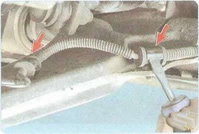
9. Disconnect the wheel speed sensor wire harness clamps from the steering knuckles.


10. Use a screwdriver to pry up the clamp brackets on the front suspension arms...
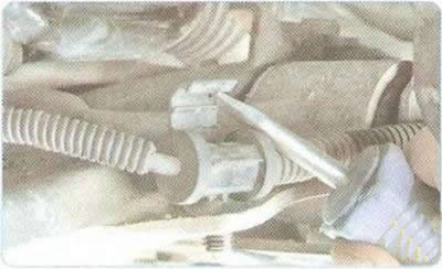


10. Use a screwdriver to pry up the clamp brackets on the front suspension arms...


11. ...fold back the staples...
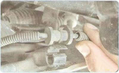
11. ...fold back the staples...


12. ...and remove the wheel speed sensor wire harnesses.
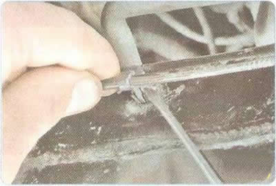
12. ...and remove the wheel speed sensor wire harnesses.


13. Press the clamps and disconnect the wheel speed sensor wire harness holders from the subframe.
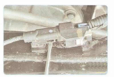
13. Press the clamps and disconnect the wheel speed sensor wire harness holders from the subframe.


14. Press the clamps...
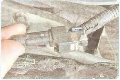


14. Press the clamps...


15. ...and disconnect the wiring harness connectors from the subframe mount.
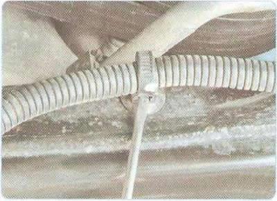
15. ...and disconnect the wiring harness connectors from the subframe mount.


16. Use a screwdriver to pry up the stoppers...
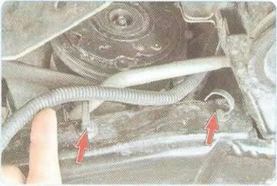
16. Use a screwdriver to pry up the stoppers...


17. ...and remove the wire harnesses from the clamps.
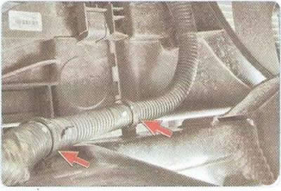
17. ...and remove the wire harnesses from the clamps.


18. Disconnect the electric fan wiring harness from the subframe.
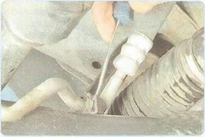


18. Disconnect the electric fan wiring harness from the subframe.


19. Use a screwdriver to pry up the retainer clip...
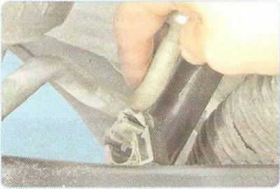
19. Use a screwdriver to pry up the retainer clip...


20. ...and disconnect the power steering line from the subframe.
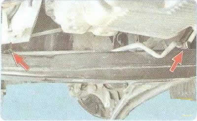
20. ...and disconnect the power steering line from the subframe.


Note: This is how the power steering line mounting clips are located on the subframe.
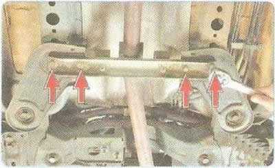

Note: This is how the power steering line mounting clips are located on the subframe.


21. Remove the four bolts securing the amplifier to the subframe bracket.
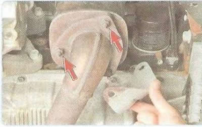


21. Remove the four bolts securing the amplifier to the subframe bracket.


22. Remove the support bracket, unscrew the two nuts securing the inlet pipe to the neutralizer (see "Removal and installation the catalytic converter") and lower the intake pipe down.
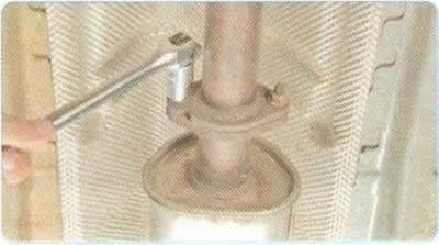
22. Remove the support bracket, unscrew the two nuts securing the inlet pipe to the neutralizer…


23. Unscrew the two nuts securing the flange of the inlet pipe to the additional muffler.

24. Disconnect the flanges of the inlet pipe and the additional muffler, remove the sealing gasket from the studs of the additional muffler flange.
24. Disconnect the flanges of the inlet pipe and the additional muffler, remove the sealing gasket…


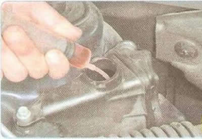
25. Drain the working fluid from the power steering reservoir (see "Replacing the working fluid and bleeding the power steering system").
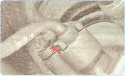
25. Drain the working fluid from the power steering reservoir (see «Replacing the working fluid and…


26. Remove the power steering pressure and drain line bolt and disconnect the lines from the steering gear.

Note: Drain the working fluid flowing out of the pipelines into a prepared container.
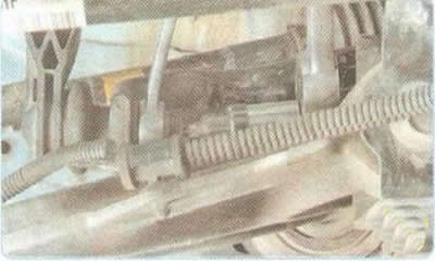

Note: Drain the working fluid flowing out of the pipelines into a prepared container.


27. Unscrew the nut securing the lower strut hinge pin to the stabilizer bar, using a second wrench to hold the pin from turning.
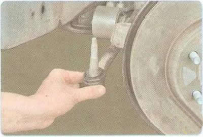
27. Unscrew the nut securing the lower strut hinge pin to the stabilizer bar, using a second wrench…


28. Remove the outer tie rod end joint pin from the steering knuckle boss (see "Replacing the outer tie rod end").
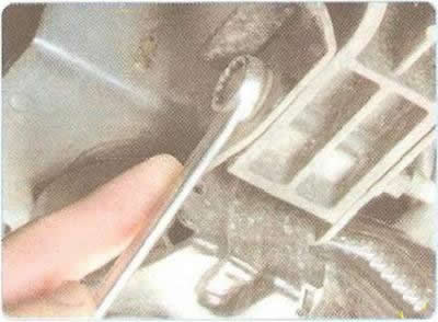
28. Remove the outer tie rod end joint pin from the steering knuckle boss (see «Replacing the outer…


29. Unscrew the bolts securing the energy-absorbing element of the bumper to the subframe on the right and left sides and remove them.
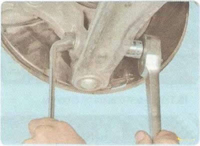
29. Unscrew the bolts securing the energy-absorbing element of the bumper to the subframe on the…


30. Loosen the nut of the clamping bolt of the terminal connection of the steering knuckle with the ball joint, holding the bolt from turning, remove the bolt and remove the ball joint pin from the steering knuckle.

31. Using the cooling fan lugs, tie the radiator and condenser to the upper cross member of the radiator frame.
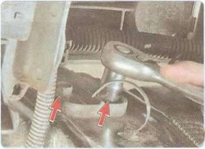
31. Using the cooling fan lugs, tie the radiator and condenser to the upper cross member of the…


32. Remove the four bolts securing the radiator bracket support (two on the right and two on the left side).
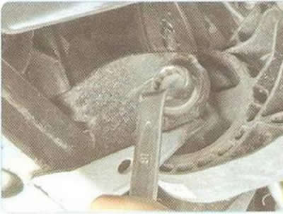
32. Remove the four bolts securing the radiator bracket support (two on the right and two on the…


33. Loosen the nuts of the front...

33. Loosen the nuts of the front...


34. ...and the rear supports of the power unit suspension to the subframe, holding the bolts from turning.

35. Remove the power unit support mounting bolts.

36. Install the support under the subframe.
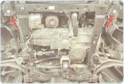
36. Install the support under the subframe.


37. Turn out the front...
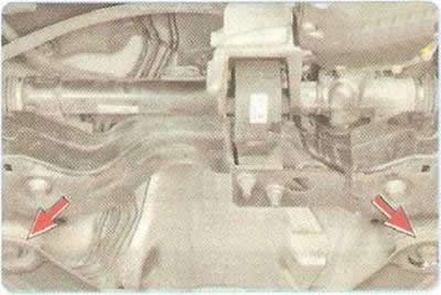
37. Turn out the front...


38. ...and the rear bolts securing the subframe to the body.
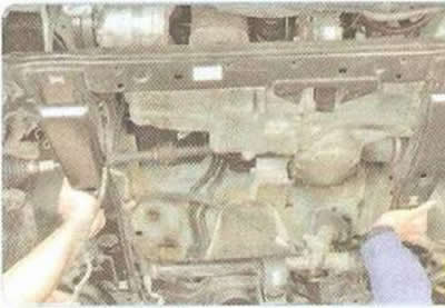
38. ...and the rear bolts securing the subframe to the body.


39. Remove the front suspension subframe (Fig. 7.3).
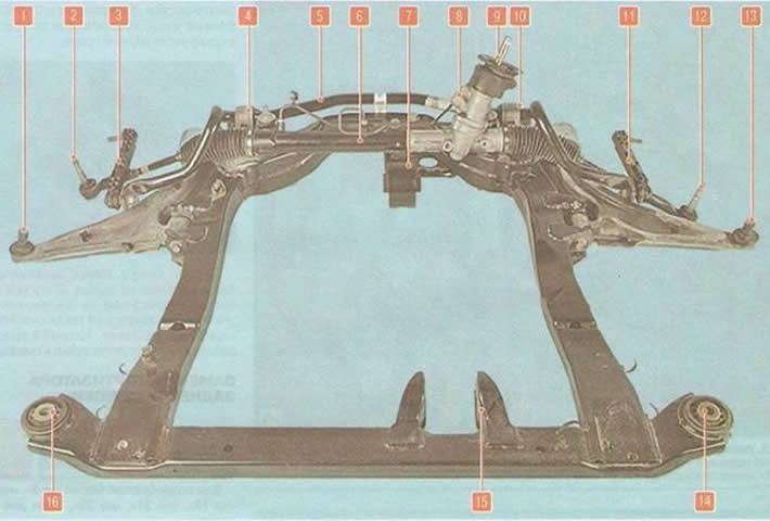
Fig. 7.3. Front suspension subframe assembled with stabilizer bar and steering gear: 1, 13 - ball…
Fig. 7.3. Front suspension subframe assembled with stabilizer bar and steering gear: 1, 13 - ball joint pins; 2, 12 - pins of the hinges of the outer ends of the steering rods; 3, 11 - stabilizer struts; 4, 10 - stabilizer bar brackets; 5 - anti-roll bar; 6 - steering mechanism; 7 - rear support of the power unit suspension; 8 - holes for fastening the power steering pipes; 9 - steering gear shaft; 14, 16 - front subframe mount supports to the body; 15 - Front support bracket for powertrain suspension


Note: The front suspension subframe is removed together with the stabilizer bar and steering gear.
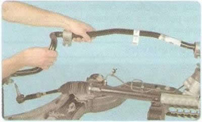

Note: The front suspension subframe is removed together with the stabilizer bar and steering gear.


40. If necessary, remove the stabilizer bar...
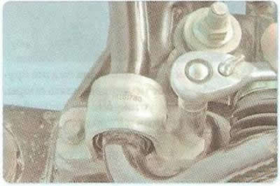
40. If necessary, remove the stabilizer bar...


41. ... having unscrewed the four bolts securing the rod brackets to the subframe (two on the right and two on the left side).
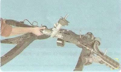
41. ... having unscrewed the four bolts securing the rod brackets to the subframe (two on the right…


42. If necessary, remove the steering gear...
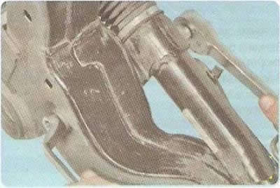
42. If necessary, remove the steering gear...


43. ... by unscrewing the nuts of the bolts securing the steering gear to the front suspension subframe on the left and right.

44. Install the parts in the reverse order of removal.

45. Bleed the power steering system (see "Replacing the working fluid and bleeding the power steering system").

Recommendation: After removing and installing the front suspension subframe, check and, if necessary, adjust the wheel alignment angles (see "Checking and adjusting wheel alignment angles"). Use the services of workshops that have special equipment.

The article was checked: Vladimir Romannikov
This article is available at russian, bulgarian, belarusian, ukrainian, serbian, croatian, romanian, polish, slovak, hungarian

Share information:

Previous articles
Cruze 1: Front suspension
Next articles

Removal and installation the front suspension steering knuckle
Replacing the front suspension stabilizer bar
Replacing the front suspension arm
Replacing the front suspension ball joint
Checking and adjusting wheel alignment angles


See similar articles on the topic of Chevrolet cars:
Removal and installation the front suspension subframe Chevrolet Aveo T200 (2003-2008)
Front suspension unit of the gearbox with the main gear assembly Chevrolet Captiva 1 (2006-2018)
Front suspension device Chevrolet Lacetti 1 (2002-2009)
Replacing the silent block and cushion of the front suspension arm Chevrolet Lanos T150 (2002-2009)
Front suspension device Chevrolet Niva 1 (2002-2016)
Front suspension shock absorber — removal and installation Chevrolet Tahoe 1 (1992-2000)
Removal and installation front suspension arms Chevrolet Lumina 1 (1989-1994)
Link in different formats to this page


Visitor comments

No comments yet


How much will 37 + 49 =


Cruze 1 (2008-2016) 
  • General information
  • User manual
  • Troubleshooting
  • Maintenance
  • Power unit
  • Engine repair
  • Lubrication system
  • Cooling system
  • Exhaust system
  • Supply system
  • Control system
  • Transmission
  • Clutch
  • Car gearbox
  • Front wheel drives
  • Chassis
  • Front suspension
  • Rear suspension
  • Steering
  • Brake system
  • Body
  • Exterior (external elements)
  • Interior (internal elements)
  • Doors, covers and windows
  • Heating and air conditioning
  • Security systems
  • Electrical equipment
  • Equipment and devices
  • Power devices
  • Lighting and signaling
  • Electrical circuits


ChevyMan.ru © 2017-2026 · Mobile version · Feedback · Site search · Interesting to read · Sitemap: EN BG BY UA RS HR RO PL SK HU

Aveo 2003-2008 · Aveo 2006-2011 · Aveo 2012-2018 · Captiva 2006-2018 · Cruze 2008-2016 · Lacetti 2002-2009 · Lanos 2002-2009 · Niva 2002-2016 · Tahoe 1992-2000 · Tahoe 2000-2014 · Lumina 1 1989-1994 · Trailblazer 1 2001-2008 · Orlando 1 2010-2018 ·
🛡️ For your security and to improve our service, this site uses cookies. You can disable them in your browser.