ChevyMan.ru
Mazda Mitsubishi Toyota Land Rover Honda Kia Nissan
English Русский
Български
Беларускі
Український
Српски
Hrvatski
Română
Polski
Slovenský
Magyar
|
Articles | Sitemap | Contacts |


Home   Aveo   Captiva   Cruze   Lacetti   Lanos   Niva   Tahoe   Others  
Cruze 1 (2008-2016)
  • Home
  • Cruze
  • J300 (2008-2016)
  • Chassis
  • Steering
  • Removal and installation the steering column

Removal and installation the steering column (Chevrolet Cruze J300)

            0

The steering column is one of the most important elements of road safety, so replace the steering column if the following defects are present:
  • deformation or damage of the intermediate shaft, play in the cardan joint, damage to its terminal connections with the steering shaft and the steering gear shaft;
  • deformation or damage of the steering shaft;
  • damage to the splines connecting the shaft to the steering wheel hub;
  • damage to the steering column adjustment mechanism.

You will need: a flat-blade screwdriver, 7, 11, and 12 mm heads.

1. Disconnect the wire from the negative terminal of the battery.

2. Remove the steering wheel (see "Removal and installation the steering wheel").
2. Remove the steering wheel (see «Removal and installation the steering wheel»).


3. Remove the steering column cover (see "Removal and installation the steering column cover" P. 187);
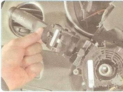
3. Remove the steering column cover (see «Removal and installation the steering column cover» P.…


4. Remove the steering column switches (see "Replacing steering column switches").
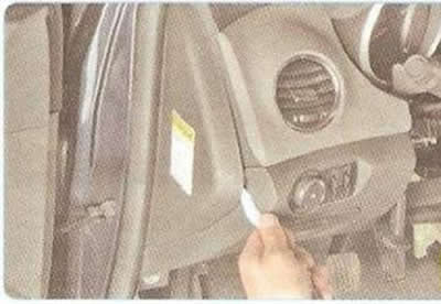


4. Remove the steering column switches (see «Replacing steering column switches»).


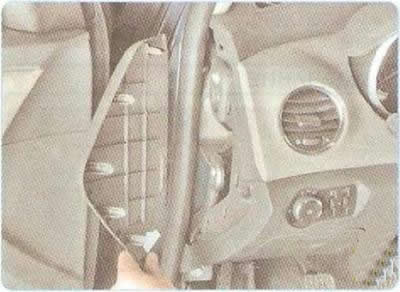
5. Pry it up with a screwdriver.

5. Pry it up with a screwdriver.


6. ...and remove the cover from the left end of the instrument panel, overcoming the elastic resistance of its clamps.

Helpful Hint: To avoid damaging the instrument panel trim surfaces, wrap the screwdriver in a cloth.
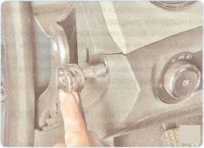

Helpful Hint: To avoid damaging the instrument panel trim surfaces, wrap the screwdriver in a cloth.


7. Remove one bolt of the upper mounting of the lower instrument panel trim, located under the cover.


8. Remove the two front bolts securing the lower instrument panel trim.
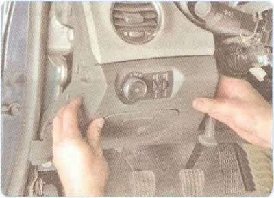
8. Remove the two front bolts securing the lower instrument panel trim.


9. Overcoming the elastic resistance of the holders, move the lower trim away from the instrument panel.
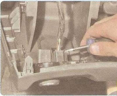
9. Overcoming the elastic resistance of the holders, move the lower trim away from the instrument…


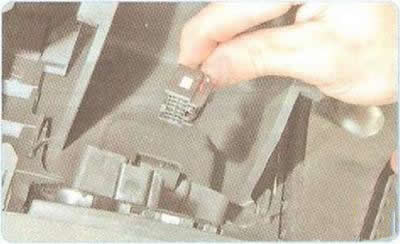
10. Slide the lock.

10. Slide the lock.


11. ...and disconnect the wiring harness connector from the control unit for external lighting, headlight range control and instrument cluster lighting.
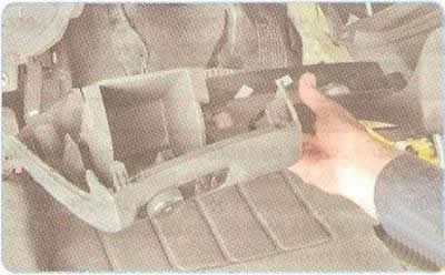


11. ...and disconnect the wiring harness connector from the control unit for external lighting,…


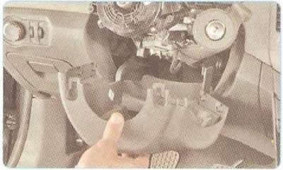
12. Remove the lower instrument panel trim.
12. Remove the lower instrument panel trim.


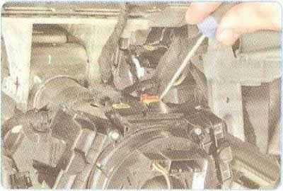
13. Use a screwdriver to pry up and slide the airbag wiring harness connector retainer.

13. Use a screwdriver to pry up and slide the airbag wiring harness connector retainer.


14. Disconnect the connector from the horn and airbag contact ring.
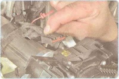
14. Disconnect the connector from the horn and airbag contact ring.


15. Disconnect the horn wire harness connector or contact ring.
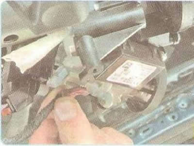


15. Disconnect the horn wire harness connector or contact ring.


16. Disconnect the wiring harness connector from the immobilizer controller.
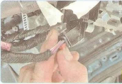
16. Disconnect the wiring harness connector from the immobilizer controller.


17. Slide the lock...
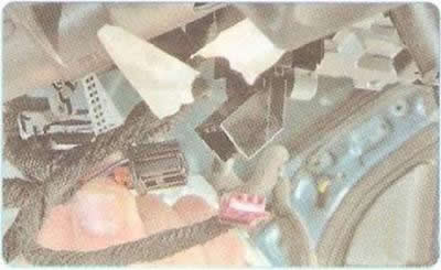
17. Slide the lock...


18. ...and disconnect the wiring harness block from the ignition switch (lock).
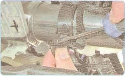
18. ...and disconnect the wiring harness block from the ignition switch (lock).


19. Press the clamps...
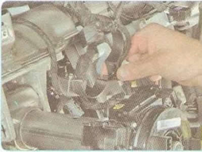


19. Press the clamps...


20. ...and remove the wiring harness bracket from the steering column housing.
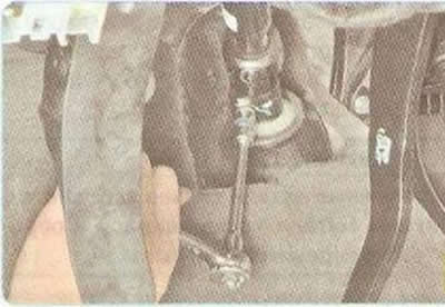
20. ...and remove the wiring harness bracket from the steering column housing.


21. Unscrew the clamp bolt of the lower universal joint clamp to the steering gear shaft and remove the joint from the steering gear shaft.

Helpful Hint: When removing the steering column, mark in any way possible the relative positions of the terminal connection of the lower cardan joint of the intermediate shaft and the steering gear shaft.


In addition, the splines of the steering gear shaft and the splines of the lower universal joint have chamfers that must be aligned during installation.
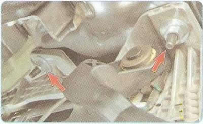

In addition, the splines of the steering gear shaft and the splines of the lower universal joint…


22. Unscrew the two nuts securing the left steering column bracket to the instrument panel amplifier.
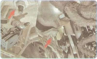
22. Unscrew the two nuts securing the left steering column bracket to the instrument panel…


23. Unscrew the two nuts securing the right-hand steering column bracket to the instrument panel amplifier.
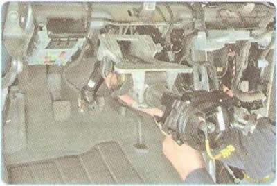
23. Unscrew the two nuts securing the right-hand steering column bracket to the instrument panel…


24. Remove the steering column while simultaneously removing the lower joint from the steering gear shaft.
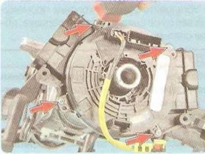
24. Remove the steering column while simultaneously removing the lower joint from the steering gear…


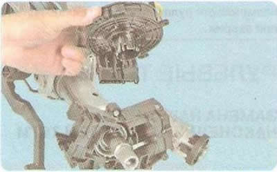
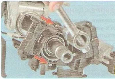
25. Remove four screws...

25. Remove four screws...


26. ...and remove the horn and airbag contact ring from the steering column.

26. ...and remove the horn and airbag contact ring from the steering column.


27. Remove the immobilizer controller (see "Replacing the ignition switch (lock) contact group and immobilizer controller").
27. Remove the immobilizer controller (see «Replacing the ignition switch (lock) contact group and…


28. Remove the two screws securing the steering column paddle connector to the steering column...
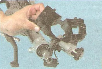
28. Remove the two screws securing the steering column paddle connector to the steering column...


29. ...and remove the connector.

30. Install the steering column, intermediate shaft and all removed parts in the reverse order of removal.

Caution: To avoid damaging the steering column when installing it, first tighten the two lower nuts securing the steering column bracket to the instrument panel reinforcement, then the two upper nuts.


Do not exceed the tightening torque of the steering column mounting nuts (in two stages: tighten to 22 Nm, then turn further by 45°), as this may adversely affect the ability of the steering column to fold in an accident.

The article was checked: Vladimir Romannikov
This article is available at russian, bulgarian, belarusian, ukrainian, serbian, croatian, romanian, polish, slovak, hungarian

Share information:

Previous articles
Cruze 1: Steering
Next articles

Removal and installation the steering column cover
Removal and installation the steering wheel
Checking the free play (play) of the steering wheel
Inspection and testing of the steering system on the vehicle
Possible malfunctions of power steering, their causes and methods of elimination
Replacing the outer tie rod end
Replacing the steering rod
Replacing the working fluid and bleeding the power steering system
Replacing the power steering fluid reservoir
Replacing the steering gear


See similar articles on the topic of Chevrolet cars:
Removal and installation the steering column cover Chevrolet Aveo T300 (2012-2018)
Diagnosing steering column faults Chevrolet Captiva 1 (2006-2018)
Steering column switches, switches, headlight corrector, instrument lighting brightness adjustment Chevrolet Lacetti 1 (2002-2009)
Steering column switches Chevrolet Lanos T150 (2002-2009)
Steering column switches Chevrolet Niva 1 (2002-2016)
Steering column boot Chevrolet Tahoe 2 and 3 (2000-2014)
Removal and installation the steering column cover Chevrolet Lumina 1 (1989-1994)
Link in different formats to this page


Visitor comments

No comments yet


How much will 40 + 23 =


Cruze 1 (2008-2016) 
  • General information
  • User manual
  • Troubleshooting
  • Maintenance
  • Power unit
  • Engine repair
  • Lubrication system
  • Cooling system
  • Exhaust system
  • Supply system
  • Control system
  • Transmission
  • Clutch
  • Car gearbox
  • Front wheel drives
  • Chassis
  • Front suspension
  • Rear suspension
  • Steering
  • Brake system
  • Body
  • Exterior (external elements)
  • Interior (internal elements)
  • Doors, covers and windows
  • Heating and air conditioning
  • Security systems
  • Electrical equipment
  • Equipment and devices
  • Power devices
  • Lighting and signaling
  • Electrical circuits


ChevyMan.ru © 2017-2026 · Mobile version · Feedback · Site search · Interesting to read · Sitemap: EN BG BY UA RS HR RO PL SK HU

Aveo 2003-2008 · Aveo 2006-2011 · Aveo 2012-2018 · Captiva 2006-2018 · Cruze 2008-2016 · Lacetti 2002-2009 · Lanos 2002-2009 · Niva 2002-2016 · Tahoe 1992-2000 · Tahoe 2000-2014 · Lumina 1 1989-1994 · Trailblazer 1 2001-2008 · Orlando 1 2010-2018 ·
🛡️ For your security and to improve our service, this site uses cookies. You can disable them in your browser.