


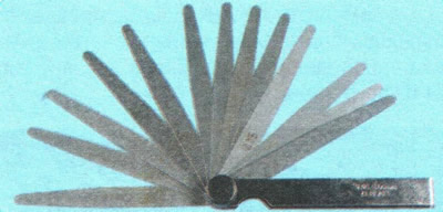
...and a set of measuring probes.
To compensate for thermal expansion of the valve, a gap is set between the end of the valve stem and the camshaft cam. With an increased gap, the valve will not open completely, and with a decreased gap, it will not close completely.
The gap is measured with a feeler gauge on a cold (at a temperature of +20°C) engine between the camshaft cams (the cam must be directed away from the pushrod) and the end surface of the valve tappet.
For a cold engine, the nominal clearance on the intake camshaft is (0.25±0.04) mm, on the exhaust shaft - (0.30±0.04) mm.
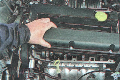
1. Remove the cylinder head cover (see "Replacing the cylinder head cover gasket").
2. Set the piston of the 1st cylinder to the TDC position of the compression stroke (see "Setting the piston of the first cylinder to the TDC position of the compression stroke"). In this case, the cams of the intake valves of the 2nd cylinder and the exhaust valves of the 3rd cylinder should be directed upwards and located symmetrically at a slight angle inward (to the center of the cylinder head).
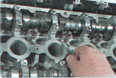
3. Measure the clearances with a set of feeler gauges. If the clearances are not within the norm, use the feeler gauges to determine the actual clearance and record the values obtained. Measure the clearances in the remaining valves in the same way. To do this, do the following:
- turn the crankshaft half a turn. In this position, check the clearances on the cams of the intake valves of the 1st cylinder and the exhaust valves of the 4th cylinder;
- turn the crankshaft half a turn again. In this position, check the clearance on the cams of the intake valves of the 3rd cylinder and the exhaust valves of the 2nd cylinder;
- turn the crankshaft another half turn and check the clearance on the cams of the intake valves of the 4th cylinder and the exhaust valves of the 1st cylinder.
4. If the clearances in the valve drive are not within the norm, adjust the clearances. To do this, replace the tappets of those valves whose clearances differ from the nominal values.
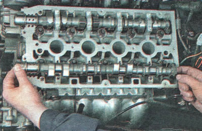
5. Remove the appropriate camshaft (see "Removal, inspection and installation of camshafts").
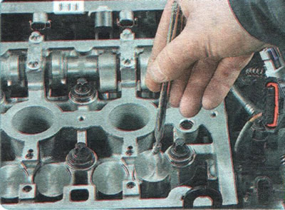
6. Remove the valve lifters.
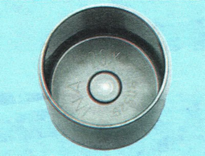
7. On the inner side of the pusher there is an index that corresponds to a certain thickness of the pusher bottom (Table 5.1). Calculate the size of the adjusting pusher N using the formula N = T + A - S (all dimensions in mm), where T is the size of the removed pusher; A - measured valve clearance; S - nominal clearance.
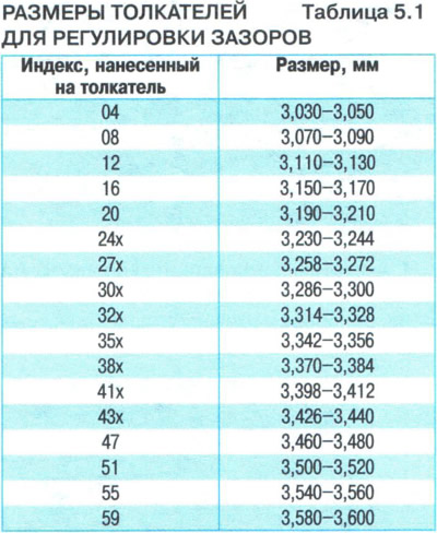
8. Install the valve lifters with the dimensions calculated by the formula and all the removed parts in the reverse order of removal, check the clearances. If necessary, repeat the operations indicated above.
The article was borrowed from the website CHEVYMAN.RU