


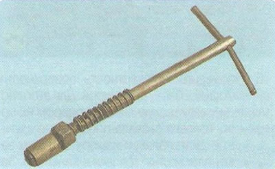
In addition, ready-made manual valve holders are available for sale.
If there are no ready-made devices, you can use a device made according to the drawing (Fig. 5.10).
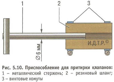
Instead of a rubber hose and clamps, you can weld a tip to rod 1 of the device, in the side wall of which a through threaded hole is made, into which a bolt is screwed to fix the valve rod.
In addition, you will need: lapping paste, kerosene, a weak spring, the outer diameter of which passes into the valve seat hole.
1. Clean the valve from carbon deposits.
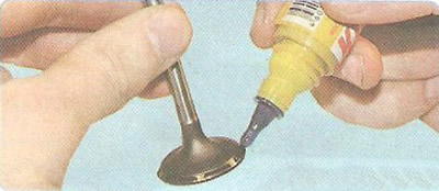
2. Apply a continuous thin layer of lapping paste to the valve chamfer.
3. Place the pre-selected spring on the valve stem and insert the valve into the guide bushing from the combustion chamber side, lubricating the valve stem with a layer of graphite grease.
Note: Graphite grease prevents the abrasive from the lapping paste from getting into the guide bushing holes and makes it easier to rotate the valve during lapping.
4. Place the valve lapping tool on the valve stem (or with some tension a rubber tube to connect the valve to the reversible drill).
5. Turn on the drill at minimum speed (in reverse mode) or by rotating the device (in case of manual lapping) alternately in both directions by half a turn, grind the valve, periodically pressing it to the seat, then weakening the pressing force.
Helpful Hint: If you don't have any tools, you can grind the valve using a hose of the appropriate diameter and a clamp, pressing and turning the valve with it.
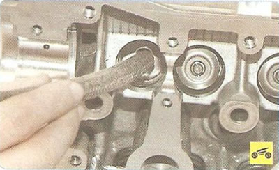
6. Grind the valve until a matte-gray continuous single-color belt appears on its chamfer, while a matte-gray belt of the appropriate size should also appear on the valve seat after grinding.
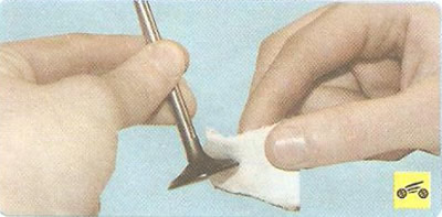
7. After lapping, thoroughly wipe the valve and seat with a clean cloth and rinse to remove any remaining lapping paste.
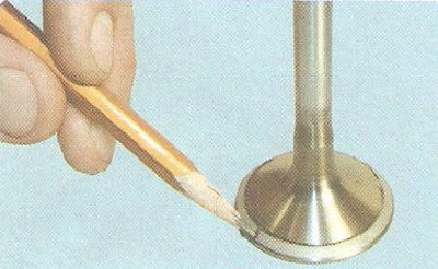
8. Check the concentricity of the valve plate and seat: apply a thin layer of pencil lead to the chamfer of the valve head, insert the valve into the guide sleeve and, pressing it lightly against the seat, turn it.
9. The graphite marks on the seat chamfer indicate the concentricity of the valve and seat.
10. Check the tightness of the valve by installing it in the head with springs and crackers. Then lay the head on its side and pour kerosene into the channel that is closed by the valve. If kerosene does not leak into the combustion chamber within 3 minutes, the valve is tight.
The article is based on data from the website: «ChevyMan»