


The engine with an overhead arrangement of two five-bearing camshafts has four valves per cylinder. The exhaust camshaft is driven by a reinforced toothed belt 2 (Fig. 5.21). The belt tension is provided by a tension roller 12.
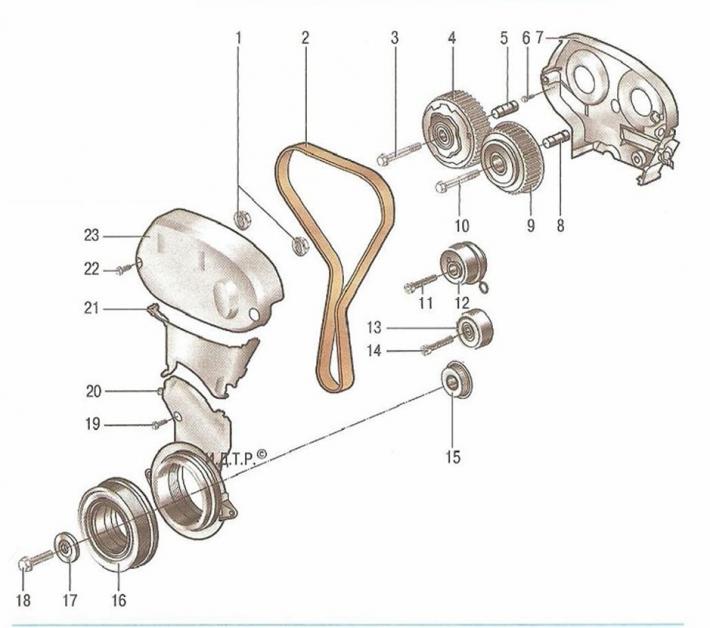
Fig. 5.21. Timing drive of the F18D engine: 1 - plug of the device for adjusting the position of the camshaft; 2 - timing belt; 3, 6, 10, 11, 14, 18, 19, 22 - bolts; 4, 9 - adjustable toothed pulleys of the camshaft; 5.8 - threaded plugs of camshaft adjusters; 7 - rear cover of the timing belt; 12 - timing belt tensioner; 13 - intermediate roller; 15 - toothed pulley of the crankshaft; 16 - crankshaft pulley; 17 - crankshaft thrust washer; 20 - lower front timing belt cover; 21 - middle front timing belt cover; 23 - Upper front timing belt cover
The engine has camshaft sprockets 4 and 9. Continuous adjustment of the camshaft pulleys is achieved by engine oil pressure. Two electromagnetic valves 33 (Fig. 5.22) regulate the oil pressure in the adjustable camshaft pulleys in accordance with commands from the engine control unit. The valve drive is equipped with piston tappets 29. The valve clearance is adjusted by installing valve tappets of the appropriate size. The engine uses conical valve springs 26. Due to their conical shape, the back pressure of the valve springs increases when they are compressed by the valve tappet, which allows the valve to immediately close again under the action of the inertia of the conventional springs after passing the bottom dead center of the camshaft cam.
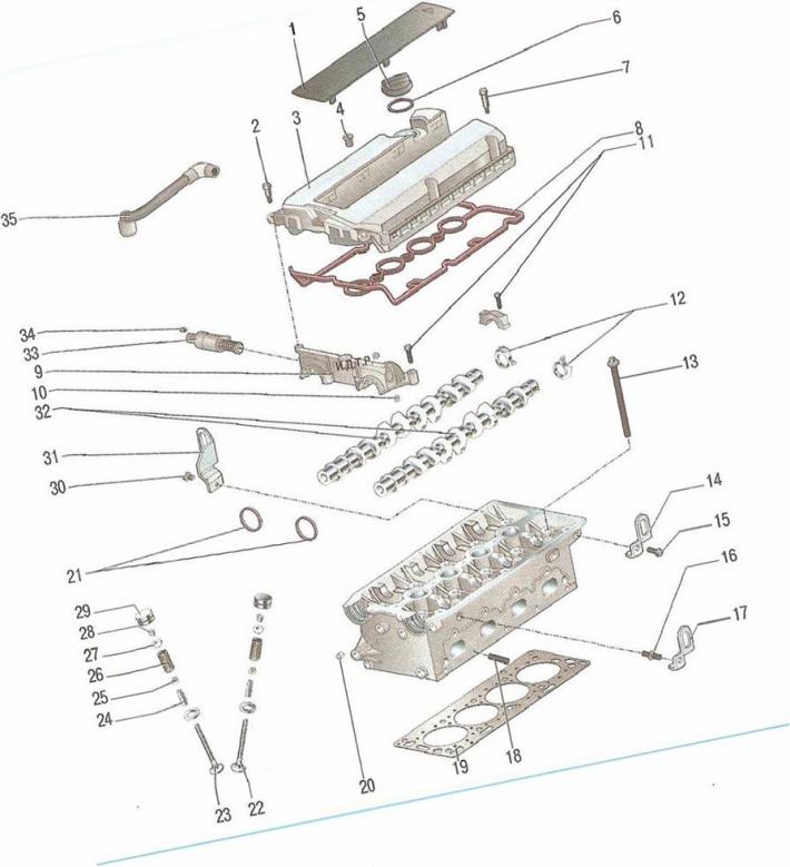
Fig. 5.22. Cylinder head of the F18D engine with a volume of 1.8 l: 1 - DIS ignition module cover; 2, 7, 11, 15, 16, 30, 34 - bolts; 3 - cylinder head cover; 4, 10, 20 - plugs; 5 - oil filler cap; b - plug sealing gasket; 8 - cylinder head cover sealing gasket; 9 - Front camshaft bearing cover; 12 - camshaft position sensor exciter; 13 - cylinder head stud; 14, 17, 31 - transport eyes; 18 - exhaust manifold finger; 19 - cylinder head gasket; 21 - Front camshaft oil seals; 22 - exhaust valve; 23 - inlet valve; 24 - valve guide; 25 - valve plate; 26 - valve springs; 27 - valve plate; 28 - valve stem oil seal; 29 - pusher; 32 - camshafts; 33 - electrohydraulic valve; 35 - forced crankcase ventilation hose
Cylinder head made of aluminum alloy with a transverse cylinder scavenging scheme (the inlet and outlet ports are located on opposite sides of the head). The valve seats and guide bushings are pressed into the heads. The inlet 23 and outlet 22 valves have one spring 26 each, fixed through plates 25 and 27.
Camshafts 32 are installed in the bearing beds made in the head body and secured with covers. The camshaft cams act on the tappets 29 through the adjusting washers, which move the valves. The plane of the head and cylinder block joint is sealed with a gasket 19 made of two plates molded from thin sheet metal and spot welded together.
Cylinder block 7 (Fig. 5.23) is a single casting forming the cylinders, cooling jacket, upper part of the crankcase and five crankshaft supports made in the form of crankcase partitions. The block is made of special high-strength cast iron with cylinders bored directly in the block body. The caps of 19 main bearings, machined together with the block, are not interchangeable. Moreover, the caps of the 1st and 2nd, as well as the 4th and 5th main bearings are made in the form of paired blocks, the caps of which are connected by bridges. These bridges play the role of additional reinforcements, serving to increase the rigidity of the cylinder block. Special bosses, flanges and holes for fastening parts, units and assemblies, as well as channels of the main oil line are made on the cylinder block. From below, the cylinder block is closed by an oil sump cast from an aluminum alloy. The plane of the joint between the cylinder block and the oil pan is sealed with a sealant; there is no removable gasket.
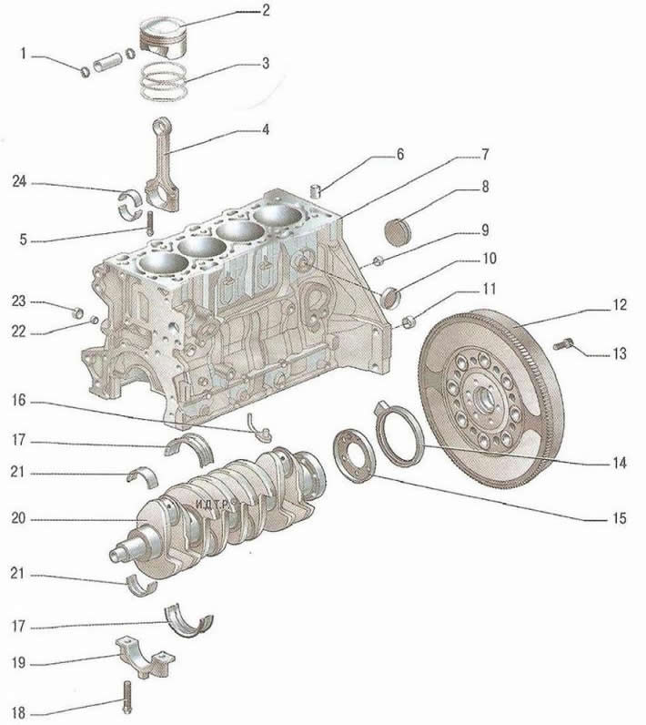
Fig. 5.23. Cylinder block, crankshaft, flywheel and oil pan of the F18D 1.8 l engine: 1 - piston pin retainer; 2 - piston; 3 - piston rings; 4 - connecting rod; 5,13,18 - bolts; 6,9,11 - mounting bushings; 7 - cylinder block; 8 - oil channel plug; 10 - water channel plug; 12 - flywheel; 14 - rear crankshaft oil seal; 15 - sensor setting disk; 16 - piston oil nozzle; 17.21 - crankshaft main bearing shells; 19 - main bearing caps; 20 - crankshaft; 22 - oil check valve; 23 - Oil check valve plug; 24 - lower and upper connecting rod bearings
The position of the crankshaft and the number of revolutions are read from the magnetic ring of the timing disk of the crankshaft speed sensor (Fig. 5.24). The timing disk is structurally combined with the seal 14 (see fig. 5.22) crankshaft.
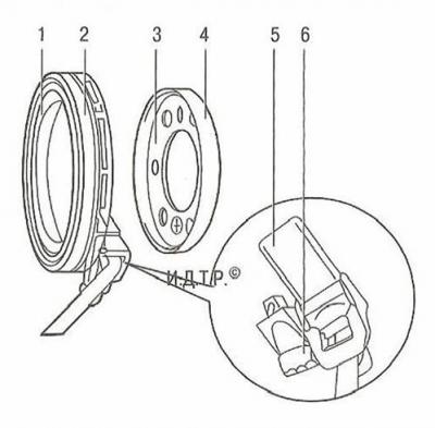
Fig. 5.24. Crankshaft speed sensor installation diagram: 1 - sealing lip of crankshaft oil seal; 2 - outer sealing surface of the crankshaft oil seal; 3 - working edge of the disk; 4 - setting disk; 5 - crankshaft sensor; 6 - crankshaft sensor mounting bolt
Crankshaft, made of steel, rotates in main bearings with thin-walled steel liners 17 (see fig. 5.23) with antifriction layer.
Flywheel 12, cast from cast iron, is installed on the rear end of the crankshaft and secured with six bolts. A toothed rim is pressed onto the flywheel for starting the engine with a starter. On cars with an automatic transmission, a leading disk of the torque converter is installed instead of a flywheel.
Pistons 5 (Fig. 5.25) are made of aluminum alloy. On the cylindrical surface of the piston head there are annular grooves for rings: two compression rings 2 and 3, as well as an oil scraper ring 4.
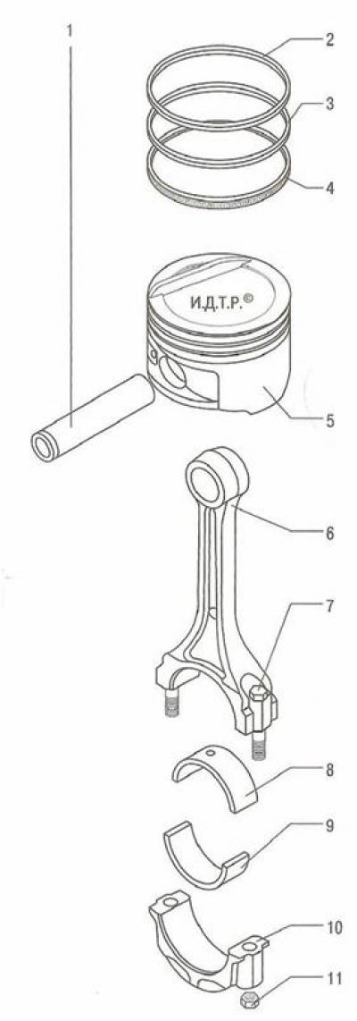
Fig. 5.25. Connecting rod and piston group of the F18D engine with a volume of 1.8 l: 1 - piston pin; 2 - upper compression ring; 3 - lower compression ring; 4 - oil scraper ring; 5 - piston; 6 - connecting rod; 7 - connecting rod bolt; 8, 9 - connecting rod bearing shells; 10 - connecting rod cover; 11 - connecting rod bolt nut
Piston pins 1 are installed in the piston bosses with a gap and are pressed with tension into the upper heads of connecting rods 6, which are connected with their lower heads to the connecting rod journals of the crankshaft through thin-walled liners 8 and 9, the design of which is similar to the design of the main bearings.
Connecting rods steel, forged, with an I-section rod.
Lubrication system combined: the most loaded parts are lubricated under pressure, and the rest - either by directed splashing or splashing of oil flowing out of the gaps between the mating parts. The pressure in the lubrication system is created by a gear oil pump 5 (Fig. 5.26), installed on the outside in the front part of the cylinder block and driven from the front end of the crankshaft. The pump is made with internal trochoidal gear engagement.
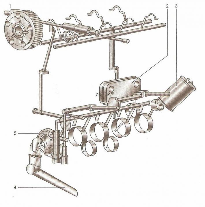
Fig. 5.26. Lubrication circuit of the F18D engine with a volume of 1.8 l: 1 - camshaft position adjuster; 2 - oil cooler; 3 - oil filter; 4 - oil receiver; 5 - oil pump
The pump sucks oil from the engine oil sump through the oil receiver 4 with a mesh filter, and then through a full-flow oil filter with a filter element made of porous paper, feeds it into the main oil line located in the cylinder block body. From the main line, oil supply channels to the crankshaft main bearings extend. Oil is supplied to the connecting rod bearings through channels made in the crankshaft body. A vertical channel for supplying oil to the camshaft bearings extends from the main oil line. In addition, oil is supplied under pressure from the engine main oil line to the variable valve timing system and to the camshaft position regulators. To lubricate the camshaft bearings, oil from the vertical channel enters the central axial channels of the camshafts through a radial hole in the journal of one of the bearings and is distributed along them to the remaining bearings.
The camshaft cams are lubricated with oil coming from the central axial channels through the radial holes in the cams. In addition, the cylinder block is equipped with nozzles for lubricating the pistons. Excess oil is drained from the cylinder head into the oil pan through vertical drainage channels.
Crankcase ventilation system closed type does not communicate directly with the atmosphere, therefore, simultaneously with the suction of gases in the crankcase, a vacuum is formed in all engine operating modes, which increases the reliability of various engine seals and reduces the emission of toxic substances into the atmosphere.
The system consists of two branches: large and small.
When the engine is idling and in low-load modes, when the vacuum in the intake pipe is high, crankcase gases are sucked in by the intake pipe through the crankcase ventilation system valve installed in the cylinder head cover along the small branch of the system. The valve opens depending on the vacuum in the intake pipe and thus regulates the flow of crankcase gases.
At full loads, when the throttle valve is open at a large angle, the vacuum in the intake pipe decreases, and in the air supply hose increases. In this case, crankcase gases through the hose of the large branch, connected to the fitting on the cylinder head cover, mainly enter the air supply hose, and then through the throttle assembly into the intake pipe and engine cylinders.
Cooling system hermetically sealed, with expansion tank 4 (Fig. 5.27), consists of a cooling jacket made of casting and surrounding the cylinders in the block, combustion chambers and gas channels in the cylinder head. Forced circulation of the coolant is provided by a centrifugal water pump 6 with a drive from the crankshaft by a poly-V belt, which also drives the generator. To maintain the normal operating temperature of the liquid in the cooling system, a thermostat 11 is installed, blocking the large circle of the system when the engine is not warmed up and the coolant temperature is low.
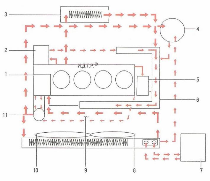
Fig. 5.27. Cooling system: 1 - coolant pump; 2 - engine oil radiator; 3 - heater; 4 - expansion tank; 5 - Exhaust gas recirculation (EGR) cooler; 6 - water pump; 7 - gearbox in block with driving axle; 8 - auxiliary cooling fan; 9 - inlet pipe; 10 - main cooling fan; 11 - thermostat
Power supply system consists of an electric fuel pump installed in the fuel tank, a throttle assembly, a fine fuel filter installed in the fuel pump module, a fuel pressure regulator, injectors and fuel lines, and also includes an air filter.
The engine is equipped with a plastic two-stage intake module (Fig. 5.28). Depending on the engine operating mode, air is directed in the plastic intake module through one of two intake tracts, which differ in length. The intake tracts are switched by a drum built into the plastic intake module. Using a switching drum for pressure by the intake channels allows reducing flow resistance in the plastic intake module at high engine speeds.
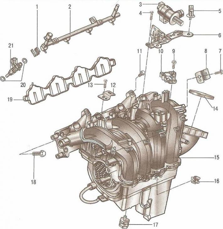
Fig. 5.28. Inlet pipe: 1 - locking bracket; 2 - fuel rail; 3 - purge valve of the adsorber; 4, 7, 9, 11, 13, 18 - bolts; 5 - Clamp of bracket of the gasoline vapor recovery system; 6 - bracket for fuel vapor recovery system; 8 - ECM wiring harness mount; 10 - absolute pressure sensor; 12 - ECM wiring harness mount; 14 - throttle body sealing ring; 15 - inlet pipe; 16 - Throttle body heating inlet hose clamp; 17 - intake pipe retainer; 19 - gasket between the intake pipe and the cylinder head; 20 - Fuel injector sealing ring; 21 - fuel injector
The throttle pipe is mounted on the side of the plastic intake module, which allows for optimal positioning of individual sections of the intake pipe and reduces air flow losses from the air filter to the intake valves. At the same time, the cross-section of the pipe remains constant along the entire length of the intake tract. The throttle pipe is sealed with a rubber ring 14.
Ignition system microprocessor, consists of an ignition coil, high-voltage wires and spark plugs. The ignition coil is controlled by an electronic engine management system unit. The ignition system does not require maintenance or adjustment during operation.
Power unit (engine with gearbox, clutch and final drive) mounted on four supports with elastic rubber elements: two upper side (right and left), bearing the main weight of the power unit, as well as the rear and front lower ones, compensating for the torque from the transmission and the loads that arise when starting the car from a standstill, accelerating and braking.
A distinctive feature of the F18D engine is its electronically controlled variable valve timing system on both camshafts (DCVCP). This system allows for the optimal valve timing to be set for each moment of engine operation, which in turn results in increased power, better fuel economy and lower exhaust toxicity.
Electrohydraulic valves 33, continuously adjusting the camshafts, are mounted on the front cover 9 (Fig. 5.22) of the camshaft bearings. Adjusting the camshaft provides an additional means of controlling the engine in the event of a change in load. At idle, the engine speed is reduced and the operating characteristics are optimized by setting the minimum valve overlap. At partial loads, the position and duration of the valve overlap are changed to ensure low fuel consumption and minimum emissions. At full load, an increase in maximum torque and power is achieved by optimizing the setting of the closing moment of the intake valves. The position of the camshaft of the intake valves changes within 60° of the crankshaft rotation angle.
When the intake camshaft is "late", the residual gas content in the cylinder is reduced because the overlap of the intake and exhaust valves is also reduced. This means that the cylinder is filled predominantly with fresh mixture.