


After disassembling, thoroughly wash the parts with kerosene, blow them out and dry them with compressed air (especially oil channels of parts).
1. Inspect the block, paying particular attention to the crankshaft bearings. Cracks in any place of the block are not allowed.
Helpful Hint: If you suspect cracks in the block (coolant entering the crankcase or oil entering the coolant), check the tightness of the unit on a special stand. Conduct the check in repair shops that have the appropriate equipment.
2. Inspect the cylinders on both sides. Scratches, burrs and cracks are not allowed.
Helpful advice: When inspecting the cylinders, we recommend illuminating the cylinder mirrors with a portable lamp - this way, defects are much more visible.
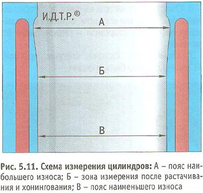
3. Determine the actual diameters of the cylinders using a bore gauge. Measure the cylinder diameter in three zones (Fig. 5.11). In each zone, the diameter is measured in two mutually perpendicular directions (longitudinal and transverse). In the area above belt A (at a distance of 5 mm from the plane of the connector with the block head) the cylinders are practically wear-free. The difference in size in this zone and in the other belts can be used to judge the wear of the cylinders. The nominal cylinder size for the F16D engine is (79±0.25) mm, for the F18D engine - (81.6±0.25) mm. The ovality and taper for the F16D engine should not exceed 0.0065 mm, for the F18D engine - 0.013 mm. If the maximum wear value is greater than 0.15 mm or the ovality exceeds the specified value, bore the cylinders to the nearest repair piston size (increased by 0.25 or 0.50 mm), leaving an allowance of 0.03 mm on the diameter for honing. Then hone the cylinders, maintaining such a diameter that when installing the selected repair piston, the calculated gap between it and the cylinder is 0.03 mm. Carry out defect detection, boring and honing of the block in workshops with special equipment.

4. Check the deviation from the flatness of the surface of the block joint with the cylinder head. Apply a caliper (or a ruler) to the plane:
- in the middle of the block;
- in transverse and longitudinal directions;
- along the diagonals of the plane. In each position, use a flat feeler gauge to determine the gap between the caliper and the plane. This will be the deviation from flatness. If the deviation is greater than 0.1 mm, replace the block.
5. Clean the piston bottom from carbon deposits with a scraper (can be made from an old file).
6. Clean the piston ring grooves from carbon deposits using an old ring by inserting it into the groove with the outer side and rolling it along the groove.
7. Inspect the pistons, connecting rods, and covers: there should be no cracks on them.
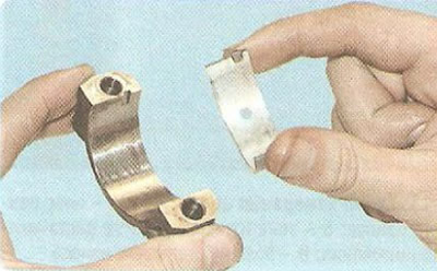
8. Inspect the bearings: if you find scratches, scoring, or delamination of the antifriction layer on the working surface, replace the bearings with new ones. All connecting rod bearings are identical and interchangeable.
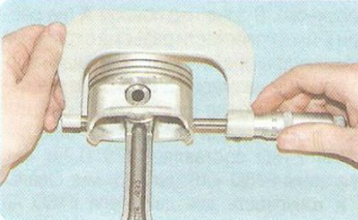
9. Measure the piston diameter in a plane perpendicular to the piston pin axis, at a distance of 19 mm from the skirt edge. The nominal piston diameter for the F16D engine is - (78.97±0.15) mm, for the F18D engine - (81.59±0.15) mm, the diameters of the repair pistons are increased by 0.25 and 0.50 mm. Based on the measurement results, determine the clearance between the piston and the cylinder, if necessary, select new pistons for the cylinders. Calculated clearance between the piston and the cylinder (for new parts) is 0.03 mm. It is determined by measuring the cylinders and pistons and is provided by installing pistons of nominal or repair sizes. The maximum permissible gap (when parts wear out) 0.15 mm. If the clearance of a used engine exceeds 0.15 mm, it is necessary to select pistons of the nominal size for the cylinders or install pistons of the repair size with boring and honing of the cylinders: the clearance should be as close as possible to the calculated one.
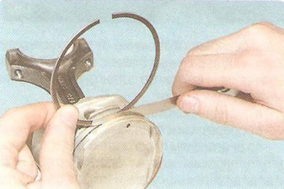
10. Check the clearance in height between the grooves in the piston and the rings with a flat feeler gauge, inserting the ring into the corresponding groove. The nominal (calculated) clearance for both compression rings is 0.020 mm. If the ring is large in height and the clearance is small, bring the ring height to the required value by grinding it on sandpaper placed on a glass plate.
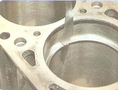
11. Check the gap in the ring lock with a flat feeler gauge by installing the ring into the cylinder to a depth of about 30 mm.
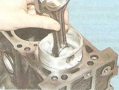
Helpful Hint: To install the ring without tilting, push the ring deeper into the cylinder with the piston.
12. The gap should be 0.3 mm for both compression rings and 0.4-1.4 mm for the oil scraper ring. If the gap is insufficient, file down the ring mating surfaces. If the gap exceeds the permissible value, replace the ring.
13. All pistons of nominal and repair sizes are manufactured with a high degree of precision and do not require preliminary sorting and selection by weight. If necessary, used pistons can be installed in individual cylinders if they are in good condition. In this case, the engine balance will not be disturbed.
14. Check the clearances between the connecting rod bearing shells and the corresponding crankshaft journals.
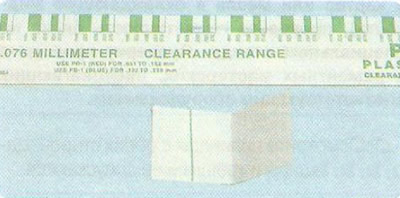
Note: The principle of gap measurement is to flatten a special plastic calibration wire and measure the width of the resulting imprint.
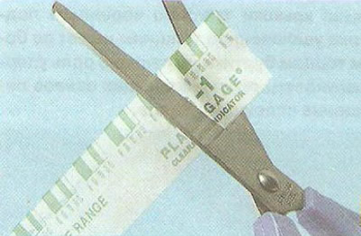
To measure the gap between the shaft journal and the bearing shells, a piece of calibration wire is used, the length of which is 2 mm shorter than the width of the bearing shell.
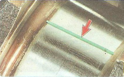
The gauge is located in the axial direction on the shaft neck...
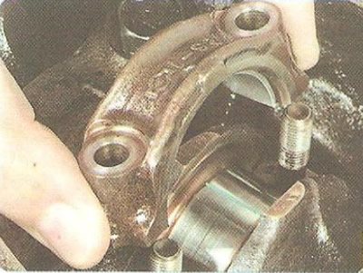
...and cover with a lid with the insert installed. To prevent the gauge from shifting when the lid is installed, it can be "glued" to the shaft journal with a thin layer of consistent grease.
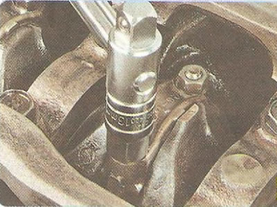
The cover nuts are tightened to the specified torque. After that, the nuts are unscrewed and the cover with the insert is carefully removed.
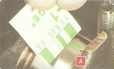
Using a special measuring template, measure the width of the imprint of the flattened calibration wire. The imprint may remain on the journal of the shaft A...
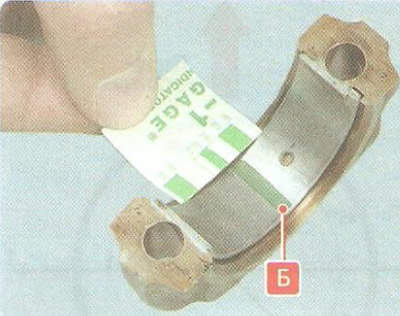
...or insert B. The gap in the connection is determined using a special conversion table applied to the template.
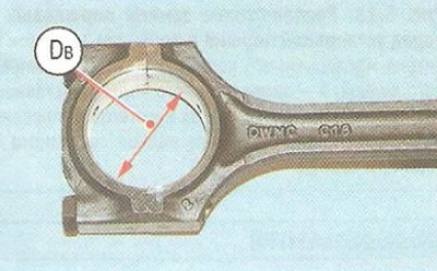
15. If there is no special calibration wire, you can use mechanical measuring devices. To do this, measure the internal diameter Db of the connecting rod seat with the cover using a bore gauge.
Note: Tighten the connecting rod bolts to the specified torque before measuring.
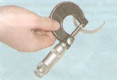
16. Measure the thickness T of the connecting rod bearings with a micrometer.
Helpful Hint: If you don't have a special attachment on your micrometer, you can use a small ball to measure the concave surface of the bearing. After measuring the bearing, subtract the diameter of the ball from the resulting size.
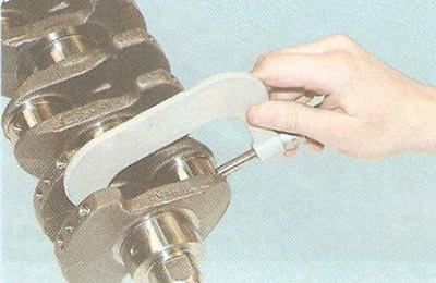
17. Measure the diameter Dh of the connecting rod journals with a micrometer.
18. Calculate the clearance z between the connecting rod inserts and the crankshaft necks using the formula z = Db-2T-Dh. The nominal design clearance is 0.019-0.070 mm. If the actual design clearance is less than the limit, you can re-use the inserts that were installed. If the gap is larger than the limit, replace the inserts on these necks with new ones (nominal thickness).
If the crankshaft journals are worn and ground to a repair size reduced by 0.25 mm, replace the liners with repair ones (increased thickness).
The journals are ground, in addition to the presence of general wear, if they have nicks and scratches or the ovality is more than 0.004 mm, and the taper is more than 0.005 mm.
Warnings: When re-grinding the crankshaft connecting rod necks to the repair size, the first cheek of the crankshaft must be marked accordingly, for example "W 0,25". Crankshafts whose neck fillers are made by knurling are not subject to re-grinding and must be replaced if the necks wear out.
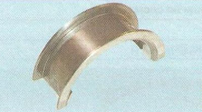
19. Inspect the upper and lower main bearing shells. The shells of the central (third) main bearing are wider than the others. In addition, their side ends have wide flanges that act as support half rings of the crankshaft thrust bearing. If there are scratches, scoring, or delamination of the antifriction layer on the working surface of the shells, replace the shells with new ones.
Warning: Do not perform any adjustment operations on the liners.
20. Inspect the crankshaft. Cracks are not allowed. There should be no scratches, nicks, or grooves on the surfaces mating with the working edges of the seals. If any are found, replace the shaft.
21. Check the clearances between the main bearing shells and the crankshaft main journals using the same procedure as for the connecting rod bearings.
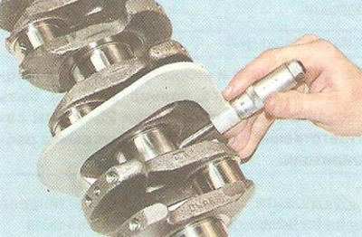
22. If there is no special calibration wire, you can use mechanical measuring devices. To do this, measure the outer diameter Dh of the root necks with a micrometer. The actual clearance between the liners of the main bearings and the root necks of the crankshaft is determined by the method described for connecting rod liners. The nominal design clearance is 0.005 mm. If the actual design clearance is less than the limit, you can re-use the inserts that were installed. If the gap is larger than the limit, replace the inserts on these necks with new ones (nominal thickness).
If the crankshaft journals are worn and ground to a repair size with a diameter reduction of 0.25 mm, replace the liners with repair ones (increased thickness).
The necks are ground, in addition to the presence of wear, if they have nicks and scratches or the ovality is more than 0.004 mm, and the taper is more than 0.005 mm, reducing the diameter by 0.25 mm.
Warnings: When regrinding the crankshaft main journals to the repair size, it is necessary to put a corresponding stamp on the first web of the crankshaft, for example, "K 0.25". Crankshafts with journal fillets made by the knurling method are not subject to regrinding and must be replaced if the journals are worn.
23. Check the parallelism of the thrust flanges of the middle main journal: if they are not parallel, the crankshaft is bent and must be replaced.
24. Flush the crankshaft channels by pouring gasoline into the radial channels, having previously plugged them on one side with wooden plugs. Wait at least 20 minutes and flush the channels with gasoline, injecting it with a rubber bulb. Remove the wooden plugs after flushing the connecting channels. If necessary, repeat flushing until clean gasoline flows out.
25. Clean the surfaces of the piston pins from varnish deposits, having softened them in a solvent beforehand. Inspect the pins. If cracks, excessive wear at the point of contact with the piston bosses and traces of turning in the upper head of the connecting rod are found, replace the pins.
Note: Piston pins and piston boss holes are manufactured with great precision. Therefore, piston pins are manufactured with a nominal diameter of 17.990-17.995 mm, providing a clearance of 0.01-0.02 mm between them and the piston boss holes.
Check the mating of the piston pin and piston by inserting a pin, previously lubricated with engine oil, into the piston boss hole. At an ambient temperature of 20°C, the pin should enter the hole when pressed with the thumb and should not fall out of the boss in the vertical position of the piston with the piston pin. A pin that falls out of the boss should be replaced with another one. If the pin falls out again, replace the piston with the pin.
Helpful Hint: If you have a new set of replacement parts, do not reuse pressed piston pins.