
You will need: the tools needed to replace the cylinder head gasket (see "Replacing the cylinder head gasket") and for replacing oil scraper caps (see "Replacing valve stem seals").
1. Disconnect the wire from the negative terminal of the battery.
2. Remove the cylinder head (see "Replacing the cylinder head gasket").
3. Remove the intake pipe (see "Replacing the intake manifold gasket"),
4. Remove the exhaust manifold (see "Replacing the exhaust manifold").
Helpful Hint: We recommend that you remove the spark plugs to avoid accidentally damaging their insulators.
5. Clean the combustion chambers from carbon deposits. Inspect the cylinder head. If there are cracks or traces of burnout in the combustion chambers, replace the head. Remove burrs and nicks on the surface of the cylinder head.
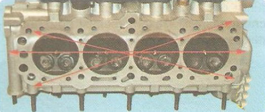
6. Check the flatness of the surface adjacent to the cylinder block. To do this, place a metal ruler with its edge on the surface of the head, first in the middle along, and then diagonally, and measure the gap between the plane of the head and the ruler with a feeler gauge. Replace the head if the gap exceeds 0.025 mm.
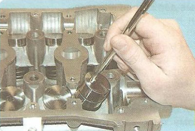
7. Remove the camshafts (see "Removal, inspection and installation of camshafts") and remove the hydraulic lifters from the cylinder head sockets.
Note: It is easier to remove the hydraulic compensator using a magnet or suction cup. The hydraulic compensators cannot be swapped, so they must be marked before removal so that they can be installed in their original places during assembly. The hydraulic compensators should be stored in the same position as they are installed on the cylinder head, so that oil does not leak out of them.
8. Clean the surfaces of the head flanges for installing the intake pipe and exhaust manifold from gasket residues and carbon deposits.
9. Check for deformations of the flanges for the intake pipe and exhaust manifold; replace the deformed head.
10. Repair damaged threaded holes by tapping the threads or installing a repair sleeve (insert).
11. Check the tightness of the cooling jacket plugs. If they become loose, restore them by hammering.
12. To check the tightness of the cylinder head, plug the hole in the head under the thermostat socket. This can be done, for example, by installing a blind gasket made of thick cardboard under the thermostat housing and screwing in the bolts for its fastening.
13. Pour kerosene into the water jacket channels. If the kerosene level decreases after 15-20 minutes, then there are cracks in the head and it needs to be replaced. After checking, do not forget to remove the cardboard gasket.
14. Check the condition of the bearing surfaces under the camshaft journals in the cylinder head. If at least one of them shows signs of wear, scoring or deep scratches, grind the bearing beds and measure the clearance between the beds and the camshaft journals after grinding. If the clearance is greater than the nominal value, replace the cylinder head.
15. To check the tightness of the valves, pour kerosene into the intake and exhaust channels of the head. If within 3 minutes the kerosene does not leak from the channels into the combustion chambers, the valves are tight. Otherwise, grind them (see "Lapping of valves") or replace the valves.
16. Place a suitable stop under the valve to be removed.
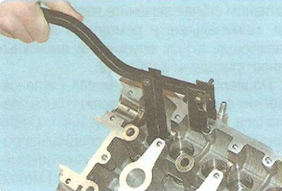
17. Install the valve spring compressor on the cylinder head. After compressing the valve springs with the compressor, remove the valve crackers. Then, gradually releasing the pressure on the compressor handle, completely release the valve spring. Remove the compressor from the cylinder head...
18. ...pry up with a screwdriver and remove the valve spring plate...
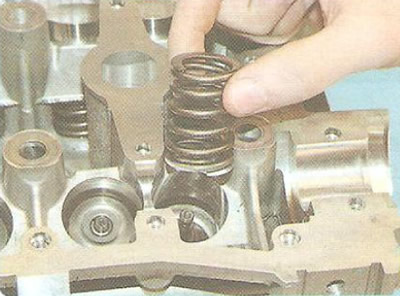
19. ...and remove the valve spring.
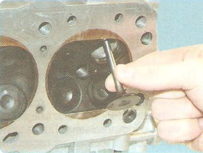
20. Remove the valve from the cylinder head.
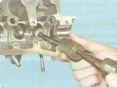
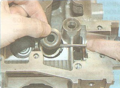
21. Install the special puller...
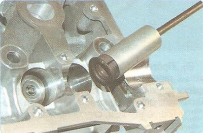
22. ...and remove the oil seal.
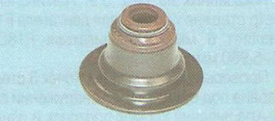
Note: The valve stem seal is made in one piece with the lower valve spring plate.
23. Remove the remaining valves in the same way and remove the oil seals.
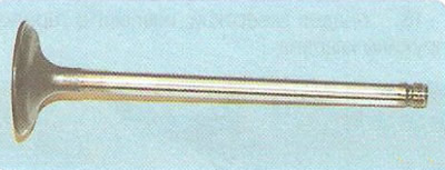
24. Remove carbon deposits from the valves and inspect them. Deformation of the valve stem and cracks on its plate are not allowed. If there is damage, replace the valve.
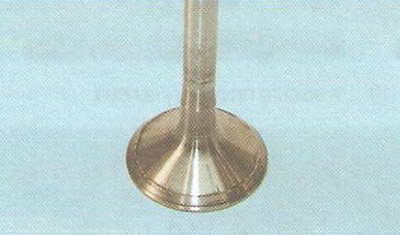
25. Check whether the working chamfer is too worn or damaged. It is permissible to grind the working chamfer of the valves (in repair shops with the appropriate equipment). After grinding, the chamfer angle relative to the plane of the valve plate of the F16D engine should be from 45° to 45°25', and of the F18D engine - 44°. Minor scratches and marks on the chamfer can be removed by grinding the valve to the seat (see Fig. "Lapping valves").
Warning: To avoid scoring the valve stems, do not clean them with wire brushes or metal scrapers.
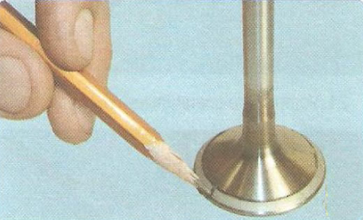
26. Check the concentricity of the valve plate and seat; apply a thin layer of graphite from a pencil lead to the chamfer of the valve head, insert the valve into the guide sleeve and, pressing it lightly against the seat, turn it.
27. The graphite marks on the seat chamfer indicate the concentricity of the valve and seat.
28. Check the valve stem wear in the areas shown in Fig. 5.9. The nominal valve stem diameter for the F16D engine is 6 mm, for the F18D engine - 5.945-5.960 mm.
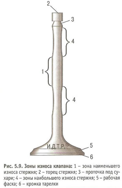
29. Check the condition of the grooves 3 of the valve stem under the crackers. If traces of chipping of the groove edges and wear of the cylindrical part are found, replace the valve.
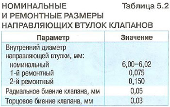
30. Check the condition of the valve guides by measuring the inner diameter of the guide bore and the diameter of the valve stem; the gap should not exceed 0.1 mm.
31. If the clearance is greater than the permissible value, repair the bushings by reaming to the repair size with an increase in the hole diameter by 0.075 mm relative to the nominal diameter. In this case, it is necessary to install valves of the corresponding repair size in them, ensuring the nominal clearance in the mating. Ream the bushing holes using a set of reamers with a guide shank. To avoid chipping the surface of the bushing, the layer of metal removed with each pass and the feed of the tool must be minimal. Otherwise, replace the guide bushings. The nominal and repair sizes of the guide bushings of the intake and exhaust valves are given in Table 5.2.
32. Check the condition of the valve seats. There should be no signs of wear, cavities, corrosion, etc. on the working chamfers of the seats. The valve seats can be replaced in a specialized workshop. Minor damage (minor scratches, marks, etc.) can be removed by grinding the valves (see "Lapping valves").
33. More significant defects of valve seats are eliminated by grinding, maintaining for F16D engine valve seats dimensions of 44.5-45° with a belt width after grinding for intake valve seats of 1.17-1.57 mm, for exhaust valve seats of 1.14-1.8 mm; for F18D engine valve seats - 44° with a belt width after grinding for intake valve seats of 1.0-1.5 mm, for exhaust valve seats of 1.7-2.2 mm. It is recommended to grind the seats in a specialized workshop, as this requires special tools and equipment. If grinding does not give the desired result, replace the valve seats.
34. Replace the valve stem seals regardless of their condition.
35. Inspect the valve springs. Cracks and loss of elasticity of the springs are not allowed. Warped springs (deformation in free state more than 1.6 mm) and replace the springs with cracks.
36. Always replace the intake manifold, exhaust manifold and cylinder head gaskets with new ones, since removed gaskets, even if not outwardly damaged, may be heavily compressed and will not ensure a tight seal.