
Contents: Removal ↧ Installation ↧
Caution: Allow the engine to cool completely before loosening the cylinder head bolts.
Note: On high mileage vehicles, during repair work, before removing the cylinder head, the camshaft cam height should be checked (detailed instructions are provided in chapter 2, Part B, Section 12).
Removal
1. Disconnect the cable from the negative terminal of the battery.
2. Remove the air filter (see chapter 4, section 8).
3. Remove the intake manifold (see section 5).
4. If it is necessary to remove the front cylinder head, unscrew the dipstick tube mounting bolt (oil level indicator).
5. Disconnect all vacuum hoses from the cylinder head. To make their installation easier, mark each one.
6. Disconnect the wires from the spark plugs and remove the spark plugs (see chapter 1, section 32). To make it easier to connect the ignition wires, mark each of them.
7. Disconnect the exhaust manifold from the cylinder head to be removed (see section 8).
8. Remove the valve covers (see section 4).
9. Remove the valve rocker arms and rods (see section 6).
10. Using a new gasket, trace the contours of the cylinder sections with holes for the bolts onto a piece of cardboard (see illustration). Don't forget to mark the front of the engine for reference (from the drive belt side). Punch holes in the locations of the bolts. Loosen the cylinder head bolts one at a time by 1/4 turn until they can be removed by hand; in this case, move from one bolt to another in the reverse order of their tightening (see illustration). As you remove the bolts, place them in a cardboard holder to ensure they are installed in the same holes they were removed from; this requirement is mandatory.
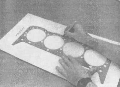
9.10a. To avoid mixing up the cylinder head bolts, use a new gasket to transfer the pattern of the threaded holes for these bolts to a cardboard template, then punch holes in the template and insert the corresponding bolts into them |
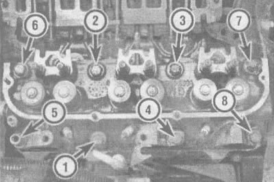
9.10b. Cylinder head bolt tightening sequence (unscrew these bolts in the reverse order) |
11. Disconnect the cylinder head(s) from the engine. If you feel resistance, do not attempt to remove the head using a lever inserted between the head and the cylinder block (for example, screwdrivers): This may cause damage to the contact surfaces. Check again that all the bolts are loose, then use a wooden block and a hammer to tap the cylinder head and try to remove it again. Be careful as the heads sit on dowel pins. As a last resort, try to detach the head using a lever installed in its rear corner; while doing this, try not to damage anything. After removing the head, place it on wooden blocks to avoid damaging the gasket surface.
12. The procedures for disassembling and checking the condition of the cylinder head, as well as servicing the cam mechanism, are presented in chapter 2, Part 2.3.
Installation
13. Before starting the installation procedure, thoroughly clean the mating surfaces of the cylinder head and block.
14. Using a scraper, remove any remaining old gasket material from the mating surfaces, then wash them with varnish cleaner or acetone. If grease remains on the mating surfaces during assembly, the gasket may not provide a sufficient seal, resulting in oil leakage. When working with the cylinder block, it is recommended to cover the recesses of the tappets with a rag to prevent contamination from entering the engine. Remove any dirt that gets into the cylinders with a rag or vacuum cleaner.
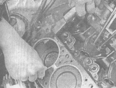
9.14. After removing the old gasket, carefully remove any remaining sealant and gasket material using a scraper
15. Check the mating surfaces of the block and cylinder head for scoring, deep scratches and other types of damage. If the damage is minor, remove it with a file; in case of severe damage, the only way to eliminate it is to machine the surface.
16. Using a tap of the appropriate diameter, tap the threads in the cylinder head bolt holes. Using a suitable die, completely thread each of the cylinder head bolts (see illustration). The presence of dirt, traces of sealant and damage to the threads will affect the tightening torque value.
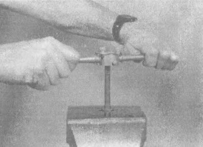
9.16 Using a suitable die, clean the threads on the mounting bolts before installing the cylinder head
17. Position the new gasket over the dowel pins in the cylinder block. On some gaskets there are inscriptions "TOR" ("Top") and "THIS SIDE UP" ("Upper side"), facilitating correct installation of the gasket during assembly (see illustrations).
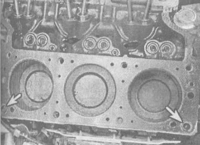
9.17a. Place the new gasket on the lips of the side pins (shown by arrows),... |
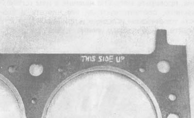
9.17b....making sure that it is facing the right way up |
18. Carefully place the head on the cylinder block, being careful not to move the gasket.
₂ or equivalent sealant to the threads and undersides of the bolt heads. Be careful when tightening the bolts: two different sizes of bolts are used to secure the cylinder head (see illustration). Using a cardboard bolt installation template will help you perform this procedure correctly.
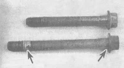
9.19. Two different sizes of bolts are used to secure the cylinder head; before tightening the bolts, apply to their threads and the lower surfaces of the heads (shown by arrows) sealant layer
20. Tighten the bolts in the recommended sequence (see illustration 9106), until the moment specified in the technical conditions given in this chapter is reached. After this, in the same sequence, tighten each bolt to the angle specified in the technical specifications.
21. The remaining operations of this procedure are performed in reverse order.
22. Replace the oil filter and fill the engine with fresh oil (see chapter 1, section 12).