
Removal
1. Remove the valve mechanism covers (caps) (see section 4) and intake manifold (see section 5).
2. Starting from the poly V-belt side, unscrew the valve rocker arm mounting nuts one by one and disconnect the valve rocker arms, nuts and rocker arm posts (see illustration). Place each rocker arm assembly separately in labeled plastic bags to avoid mixing them up when installing the assembly.
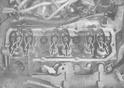
6.2. Unscrew the valve rocker arm nuts (shown by arrows)
Note: If you only need to remove the rocker arms, loosen the rocker arm nuts and rotate the rocker arms to make room to remove the rocker arms.
3. After removing the rods, store them separately to avoid confusion during installation (see illustration).

6.3. A cardboard box with holes can be used to store the valve stems; this will ensure that they are installed correctly. The inscription on the box indicates the direction to the gearbox
Note: When assembling the unit, keep in mind that the intake and exhaust manifold rods have different lengths.
Examination
4. Inspect each rocker arm for wear, cracks or other damage, especially where the rocker arms and valve stems meet.
5. Check the condition of the hinge sockets and the surface of the struts in all valve rocker arms. Look for signs of metal abrasion, cracks in stress areas and unusual wear patterns. If the valve rocker arms are worn or damaged, replace them with new ones; install new struts at the same time.
6. Make sure that the holes in all rocker arms on the rocker arm mounting side are not clogged.
7. Check the rods for cracks and signs of severe wear. Roll each rod across the glass to check for bending.
Installation
8. Apply a coat of motor oil or molybdenum sulfide grease to the lower ends of the valve stems and install them in their places. Make sure each one is fully seated in the push rod socket.
9. Apply a coat of molybdenum-based grease to the ends of the valve stems and the top ends of the valve rods.
10. To avoid damage to mating surfaces, apply a layer of molybdenum-based grease to the struts before establishing operating pressure in the engine. Install the rocker arms, struts and tighten the nuts as follows: With piston #1 at TDC, tighten the intake valve adjusting nuts an additional 1-1/2 turns after reaching zero valve clearance for cylinders 1, 5 and 6. Do the same with the exhaust valves for cylinders 1, 2 and 3. After tightening the nuts, make sure the rods are properly seated in the rocker arms. Then set the piston of the 4th cylinder to the TDC position and tighten the adjusting nuts of the intake valves by 1-1/2 turns after reaching the zero clearance point for cylinders 2, 3 and 4 and do the same with the exhaust valves for cylinders 4, 5 and 6.
Note: The zero clearance point is reached when the piston rod no longer turns easily with the rocker arm nut tightened.
11. Install the valve covers and intake manifold.