
ChevyMan.ru
Mazda Mitsubishi Toyota Land Rover Honda Kia Nissan
English Русский
Български
Беларускі
Український
Српски
Hrvatski
Română
Polski
Slovenský
Magyar
|
Articles | Sitemap | Contacts |


Home   Aveo   Captiva   Cruze   Lacetti   Lanos   Niva   Tahoe   Others  
Orlando 1 (2010-2018) Trailblazer 1 (2001-2008, petrol) Lumina 1 (1989-1994)
  • Home
  • Chevrolet
  • Lumina 1
  • Power unit
  • Engine 3.1L V6
  • Removal and installation the intake manifold

Removal and installation the intake manifold (Chevrolet Lumina 1)

            0

Contents: Removal ↧ Installation ↧

Removal


1. Relieve the pressure in the fuel supply system (see chapter 4, section 2).

2. Disconnect the cable from the negative terminal of the battery.

3. Drain the coolant (see chapter 1, section 29).

4. Disconnect the upper radiator hose from the thermostat housing. If the intake manifold needs to be replaced, remove the thermostat (see chapter 3, section 3).

5. Disconnect the electrical connectors of the coolant temperature sensor and the exhaust gas recirculation (EGR) temperature switch (see chapter 6, sections 4 and 7).

6. If you are going to replace the intake manifold, remove the throttle body (see chapter 4, section 12); if you plan to reuse the intake manifold, there is no need to remove the throttle body.

7. If you are going to replace the intake manifold, remove the EGR valve (see chapter 6, section 7).

8. Remove the valve covers (see section 4).

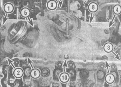
9. Loosen the intake manifold mounting bolts (see illustration) and remove the manifold. Do not insert a lever between the manifold and heads as this may damage the soft aluminum sealing surfaces of the gasket. If you are installing a new manifold, transfer all parts and sensors to it.
5.9. The intake manifold is secured with nine bolts and two nuts (shown by arrows); the numerical…

5.9. The intake manifold is secured with nine bolts and two nuts (shown by arrows); the numerical sequence shown in the illustration is only valid for tightening the intake manifold bolts (nuts) during assembly - they should be loosened in the reverse order


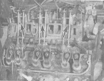
10. Cut the old intake manifold gaskets as shown in the illustration; take them off.
5.10 To remove the old intake manifold gaskets (or install new ones), cut the old gaskets in places…

5.10 To remove the old intake manifold gaskets (or install new ones), cut the old gaskets in places (shown by arrows) behind the bars, where they run in narrow strips behind the bars


Installation


Note: The mating surfaces of the cylinder head, cylinder block and manifold must be perfectly clean before installing the manifold.


11. Use a scraper to remove traces of sealing material and gaskets, then clean the mating surfaces with lacquer thinner or acetone. If traces of sealant or grease remain on the mating surfaces when the manifold is installed, oil leakage may occur through these areas. Use a vacuum cleaner to remove any gasket material that may have fallen into the intake ports or tappet recesses.

12. Clean the threads in the holes with a tap of the appropriate size, then remove the chips from the holes with a jet of compressed air.

Caution: When using compressed air, wear safety glasses or a shield to protect your eyes!


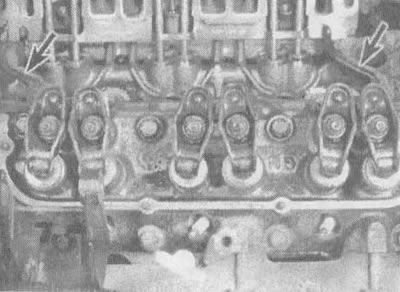
13. Apply a 3/16-inch (5 mm)drop of room-temperature vulcanizing RTV sealant to the front and rear cylinder block ridges running between the cylinder heads (see illustration).


5.13. Apply a drop of sealant to the edges between the cylinder heads (shown by arrows) or install…

5.13. Apply a drop of sealant to the edges between the cylinder heads (shown by arrows) or install seals on them


Note: Some gasket kits have face seals that can be used here in place of the sealant.


14. Cut new intake manifold gaskets in the same places where the old ones were cut and install them.

15. Carefully lower the manifold into place and tighten the bolts (nuts) by hand.

16. Tighten the bolts (nuts) in two stages, following the sequence shown in Illustration 5.9, until they are all tightened to the required torque specified in the "Tightening Torques" section of this chapter.

17. Install the remaining parts in reverse order.

18. Change the oil and oil filter, fill the cooling system (see chapter 1, sections 12 and 29). Start the engine and check the system for leaks.

The article was checked: Vladimir Romannikov
This article is available at russian, bulgarian, belarusian, ukrainian, serbian, croatian, romanian, polish, slovak, hungarian

Share information:

Previous articles
Lumina 1: Engine 3.1L V6
Next articles

Removal and installation valve covers
Setting piston N1 to TDC position
Repair work performed without removing the engine
General information about engine repair
Technical data of the 3.1 liter engine (V6)
Removal, checking and installation valve rocker arms and stems
Replacement of springs, retainers and valve seals
Removal and installation of exhaust manifolds
Removal and installation the cylinder head
Removal, inspection and installation of hydraulic valve lifters


See similar articles on the topic of Chevrolet cars:
Replacing the intake manifold gasket Chevrolet Aveo T300 (2012-2018)
Intake manifold — removal and installation Chevrolet Captiva 1 (2006-2018)
Replacing the intake manifold gasket Chevrolet Cruze 1 (2008-2016)
Removal the absolute air pressure sensor in the intake manifold Chevrolet Lacetti 1 (2002-2009)
Checking the intake manifold air temperature sensor Chevrolet Lanos T150 (2002-2009)
Intake manifold — removal and installation Chevrolet Tahoe 1 (1992-2000)
Link in different formats to this page


Visitor comments

No comments yet


How much will 35 + 38 =


Orlando 1 (2010-2018) 
  • General information
  • Introduction to manual
  • User manual
  • Maintenance
  • Troubleshooting
  • Power unit
  • Engine repair
  • Fuel and control system
  • Cooling and lubrication system
  • Ignition system
  • Transmission
  • Clutch
  • Gearbox
  • Drive shafts
  • Chassis
  • Car suspension
  • Steering
  • Brake system
  • Body
  • Exterior (external elements)
  • Doors, locks and windows
  • Electrical equipment
  • Equipment and devices
  • Windscreen wipers
  • Power devices
  • Electrical diagrams


Trailblazer 1 (2001-2008) 
  • General information
  • User manual
  • Troubleshooting
  • Maintenance
  • Power unit
  • Engine in a car
  • Engine overhaul
  • Cooling and heating
  • Fuel and exhaust system
  • Engine electrical equipment
  • Engine control
  • Transmission
  • Automatic gearbox
  • Transfer case
  • Drive shafts and cardan
  • Chassis
  • Brake system
  • Car suspension
  • Steering
  • Body
  • Exterior (external elements)
  • Interior (internal elements)
  • Doors, locks and windows
  • Electrical equipment
  • Equipment and devices
  • Electrical circuits


Lumina 1 (1989-1994) 
  • General information
  • Maintenance
  • Power unit
  • Engine 3.1L V6
  • Engine 3.8L V6
  • Engine overhaul
  • Cooling system
  • Power and exhaust system
  • Fuel injection
  • Engine electrical equipment
  • Reduced exhaust gas toxicity
  • Transmission
  • Automatic gearbox
  • Drive shafts
  • Chassis
  • Brake system
  • Car suspension
  • Steering
  • Body
  • Heating and air conditioning
  • Repair of body elements
  • Doors, covers and windows
  • Interior (internal elements)
  • Electrical equipment
  • Equipment and devices
  • Electrical circuits


ChevyMan.ru © 2017-2026 · Mobile version · Feedback · Site search · Interesting to read · Sitemap: EN BG BY UA RS HR RO PL SK HU

Aveo 2003-2008 · Aveo 2006-2011 · Aveo 2012-2018 · Captiva 2006-2018 · Cruze 2008-2016 · Lacetti 2002-2009 · Lanos 2002-2009 · Niva 2002-2016 · Tahoe 1992-2000 · Tahoe 2000-2014 · Lumina 1 1989-1994 · Trailblazer 1 2001-2008 · Orlando 1 2010-2018 ·
🛡️ For your security and to improve our service, this site uses cookies. You can disable them in your browser.