


Contents: Removal procedure ↧ Installation procedure ↧
Removal procedure
1. Disconnect the negative battery cable.
2. Remove the decorative cover. See "Decorative cover" in this section.
3. Remove the air intake hoses and ducts. See "Air injection system" in this section.
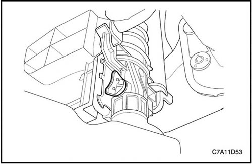
4. Disconnect the lower radiator hose and drain the coolant. See Section 1D1, "Engine Cooling - 2.0 Diesel".
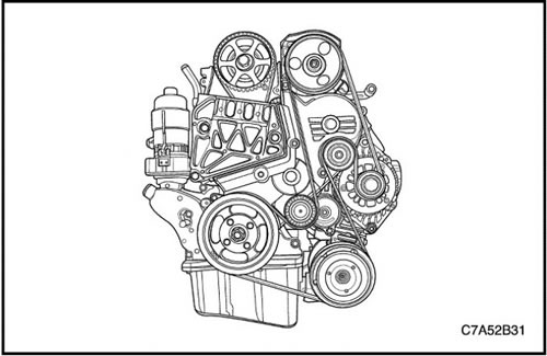
5. Remove the auxiliary belt. See "Accessory Drive Belt and Tensioner" in this section.
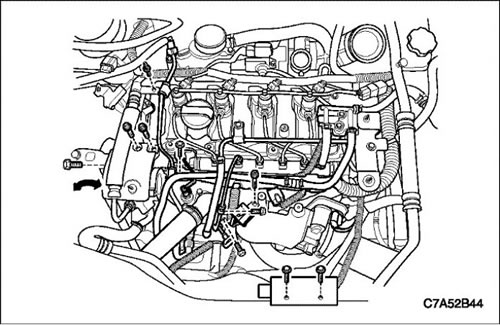
6. Remove the fuel line to the injection pump from the fuel injection pump.
7. Remove the power steering pump fastener and move it to the left side.
8. Remove the coolant hose from the intake manifold.
9. Remove the upper radiator hose.
10. Remove the return hose of the injection pump.
11. Remove the oil level indicator tube.
12. Remove the common rail fuel line located between the common rail and the fuel injection pump. See Section 1F1, Engine Controls - 2.0 Diesel.
13. Unscrew the clamping bolt of the wire connector from the intake manifold.
14. Loosen the locking bolts of the glow plug fuse box.
15. Remove the engine wiring.
- Disconnect the common rail pressure sensor connector.
- Disconnect the CTS connector.
- Disconnect the injection pump connector.
- Disconnect the generator connector.
- Disconnect the air conditioning compressor connector.
- Disconnect the starter solenoid wire connector.
- Disconnect the cooling system fan connectors.
- Disconnect the T-MAP sensor connector.
- Disconnect the camshaft position sensor connector
- Disconnect the ETC housing connector.
- Disconnect the common rail fuel regulator connector.
16. Remove the engine wiring harness guide.

17. Remove the coolant bypass hose.
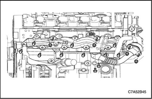
18. Remove the EGR cooler outlet pipe.
19. Remove the intake manifold with the gasket.
Installation procedure
1. Install the exhaust manifold with a new gasket.
2. Install the EGR cooler outlet pipe.
Tighten
Tighten the intake manifold bolts and nuts to 23 Nm (17 ft·lbs).
Tighten the EGR cooler outlet pipe mounting bolts and nuts to 20 Nm (14.8 ft·lbs).
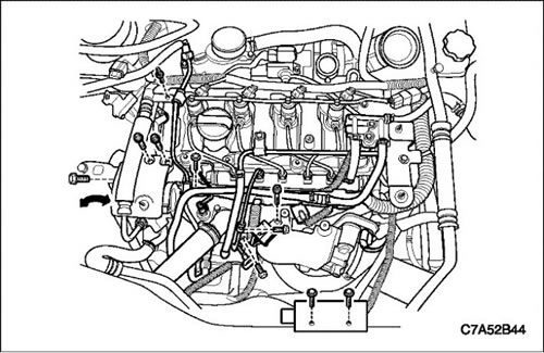
3. Install the engine wiring.
4. Tighten the glow plug fuse box retaining bolts.
5. Tighten the tightening bolt of the engine wire connector on the intake manifold.
6. Install the common rail fuel line located between the common rail and the fuel injection pump. See Section 1F1, Engine Controls - 2.0 Diesel.
7. Install the oil level indicator tube.
8. Install the power steering pump.
9. Install the fuel line to the injection pump onto the fuel injection pump.
Tighten
Tighten the glow plug fuse box bolts to 10 Nm (88.5 lbs.in).
Tighten the engine wiring harness connector clamp bolt to 15 Nm (11.1 ft·lbs).
Tighten the fuel line fastening nut to the common fuel rail to 20 Nm (14.8 ft·lbs).
Tighten the bolt securing the fuel line to the common fuel rail to 10 Nm (88.5 lbs.in).
Tighten the oil level indicator tube bolts to 11 N·m (97.4 lbs.in).
Tighten the steering pump bolts to 25 Nm (18.4 ft·lbs).
Tighten the bolt securing the fuel line to the injection pump (to the intake manifold) up to 9 Nm (79.7 lbs.in).
Tighten the fuel line mounting bolt to the injection pump to 25 Nm (18.4 ft·lbs).
[The original source of the article is the website «chevyman.ru»]