
ChevyMan.ru
Mazda Mitsubishi Toyota Land Rover Honda Kia Nissan
English Русский
Български
Беларускі
Український
Српски
Hrvatski
Română
Polski
Slovenský
Magyar
|
Articles | Sitemap | Contacts |


Home   Aveo   Captiva   Cruze   Lacetti   Lanos   Niva   Tahoe   Others  
Captiva 1 (2006-2018)
  • Home
  • Captiva
  • 1 (2006-2018)
  • Engine 2.0 l (diesel)
  • Control and power systems
  • High pressure fuel supply lines

High pressure fuel supply lines (Chevrolet Captiva 1)

            0

Contents: Removal procedure ↧ Installation procedure ↧

Removal procedure


Caution! Do not smoke or use open flames in areas where work is being performed on the fuel system. When working on the fuel system, disconnect the negative battery cable except for those checks that require battery voltage.


1. Remove the decorative cover. See Section 1B, "Engine Mechanical System - 2.0 Diesel".

2. Remove the supercharged air system. See Section 1B, "Engine Mechanical System - 2.0 Diesel".
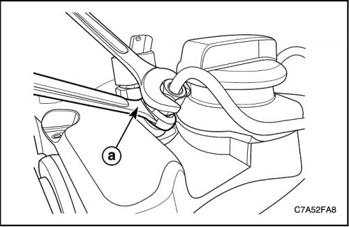
2. Remove the supercharged air system. See Section 1B, «Engine Mechanical System - 2.0 Diesel».


3. While holding the injector coupling (a), unscrew the nut (M14) securing the fuel line to the injector.

Caution! To avoid fuel spillage or damage from the injector coupling, hold the injector coupling with tools and unscrew the tube nut. And then, immediately after removing the fuel lines, put the cap on the injector connector to avoid contamination with dust. Even a small amount of dust can clog the injectors.
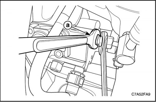

Caution! To avoid fuel spillage or damage from the injector coupling, hold the injector coupling…


4. Holding the injection pump coupling (a), unscrew the nut (M14) securing the fuel line to the common fuel rail.


Caution! To avoid fuel spillage or damage from the injection pump coupling, hold the injection pump coupling with tools and unscrew the nut (M14) securing the fuel line to the common fuel rail. And then, immediately after removing the fuel lines, put the cap on the injection pipe connector to prevent contamination with dust. Even a small amount of dust can clog the injectors.
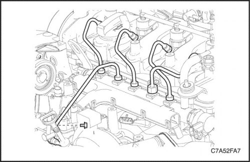

Caution! To avoid fuel spillage or damage from the injection pump coupling, hold the injection pump…


5. Unscrew the nut securing the fuel line to the common fuel rail (M17).

6. Remove the bolt securing the fuel line to the common fuel rail from the thermostat housing.

7. Remove the tube from the fuel line to the common fuel rail and the tubes from the fuel line to the injectors.

Caution! Immediately after removing the threaded connections, put caps on the threaded connections of the pipes of the common fuel rail to avoid contamination with dust. Even a small amount of dust can clog the injectors.


Installation procedure


Important: Fuel lines cannot be reused. Reusing contaminated lines may cause damage to injectors or leaking lines.


Caution! Fuel lines cannot be reused. Reusing contaminated lines may cause damage to injectors or leaking lines.


Caution! Do not wipe with napkins inside the injector couplings, injection pump and threaded connections of the pipes of the common fuel rail. If dirty, wipe the dusty area with oiled paper.


1. If the threaded connection of the common fuel rail tube is dirty, clean it with oiled paper.

2. Loosen the injector bracket bolts. See "Nozzle" in this section.
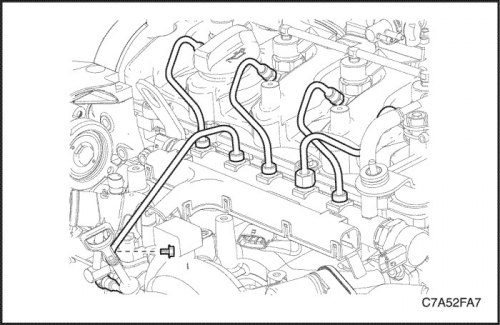
2. Loosen the injector bracket bolts. See «Nozzle» in this section.


3. Install the fuel lines between the injectors and the common rail and hand tighten the nuts.

Caution! Do not tighten the fuel line nuts with a tool.


4. Tighten the injector bracket bolts.

Tighten

Tighten the injector bracket bolt to 28 Nm (20.7 ft·lbs).
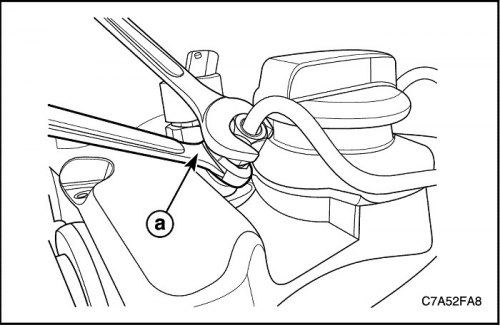
Tighten the injector bracket bolt to 28 Nm (20.7  ft·lbs).


5. While holding the injector coupling (a), tighten the nut (M14) securing the fuel line to the injector.


Tighten

Tighten the nut (M14) securing the fuel line to the injector to 27 Nm (19.9 ft·lbs).

6. Tighten the nut (M17) securing the fuel line to the injector.

Tighten

Tighten the nut (M17) securing the fuel line to the injector to 20 Nm (14.8 ft·lbs).
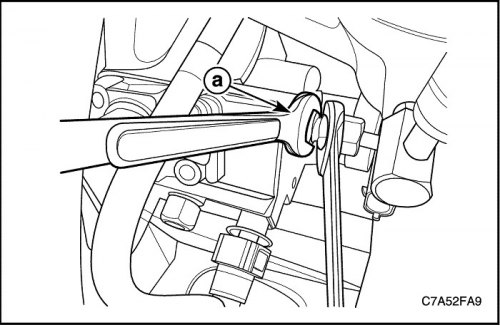
Tighten the nut (M17) securing the fuel line to the injector to 20 Nm (14.8  ft·lbs).


7. Install the fuel line between the common rail and the injection pump and hand tighten the nuts.

Caution! Do not tighten the fuel line nuts with a tool.


8. While holding the injection pump coupling (a), tighten the nut (M14) securing the fuel line to the common fuel rail.

Tighten

Tighten the nut (M14) securing the fuel line to the common fuel rail to 20 Nm (14.8 ft·lbs).

9. Tighten the nut (M17) securing the fuel line to the common fuel rail.

Tighten

Tighten the nut (M17) securing the fuel line to the common fuel rail to 20 Nm (14.8 ft·lbs).
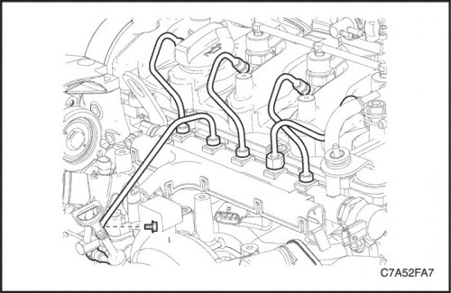
Tighten the nut (M17) securing the fuel line to the common fuel rail to 20 Nm (14.8  ft·lbs).


(The original article can be found on the resource «chevyman»)

The article was checked: Vladimir Romannikov
This article is available at russian, bulgarian, belarusian, ukrainian, serbian, croatian, romanian, polish, slovak, hungarian

Share information:

Previous articles
Captiva 1: Control and power systems
Next articles

Fuel Filter / Water Sensor / Fuel Temperature Sensor
Fuel level sensor
Fuel pump assembly
Fuel tank — removal and installation
Visual inspection of fuel pressure (low pressure line)
Fuel injection pump
Common rail fuel
Common Rail Pressure Sensor
Common Rail Regulator
Fuel return line assembly


See similar articles on the topic of Chevrolet cars:
Checking the pressure in the fuel system Chevrolet Aveo T300 (2012-2018)
Checking the tightness of fuel lines Chevrolet Cruze 1 (2008-2016)
Replacing the fuel filter Chevrolet Lacetti 1 (2002-2009)
Checking the pressure in the engine fuel system Chevrolet Lanos T150 (2002-2009)
Fuel tank cap Chevrolet Niva 1 (2002-2016)
Fuel Pump/Fuel Pressure — Check Chevrolet Tahoe 1 (1992-2000)
Fuel pressure relief Chevrolet Lumina 1 (1989-1994)
Link in different formats to this page


Visitor comments

No comments yet


How much will 29 + 49 =


Captiva 1 (2006-2018) 
  • Manual
  • Before leaving
  • Keys, doors and windows
  • Seats, protection systems
  • Instruments and controls
  • Lighting system
  • Information and entertainment
  • Navigation system
  • Climate control
  • Driving a car
  • Car care
  • Maintenance
  • Engine 2.0 l (diesel)
  • Engine device
  • Troubleshooting
  • Engine repair
  • Cooling system
  • Engine electrical equipment
  • Control and power systems
  • Exhaust system
  • Engine FAM II 2.4D
  • Engine device
  • Troubleshooting
  • Engine repair
  • Cooling system
  • Engine electrical equipment
  • Control and power systems
  • Exhaust system
  • Engine HFV6 3.2L
  • Engine device
  • Troubleshooting
  • Engine repair
  • Cooling system
  • Engine electrical equipment
  • Control and power systems
  • Exhaust system
  • Transmission
  • Front drive axle
  • Rear drive axle
  • Automatic gearbox - device
  • Automatic gearbox - service
  • Automatic gearbox - repair
  • Manual gearbox - device
  • Manual gearbox - service and repair
  • Clutch
  • Transfer case
  • Chassis
  • Car suspension
  • Brake system
  • Steering
  • Body
  • Heating and ventilation
  • Air conditioning (manual)
  • Air conditioning (automatic)
  • Seat belts
  • Airbags
  • Car seat
  • Interior (internal elements)
  • Exterior (external elements)
  • Doors and windows
  • Electrical equipment
  • Equipment and devices
  • Lighting and lamps
  • Windshield wipers and washers
  • Electrical circuits


ChevyMan.ru © 2017-2026 · Mobile version · Feedback · Site search · Interesting to read · Sitemap: EN BG BY UA RS HR RO PL SK HU

Aveo 2003-2008 · Aveo 2006-2011 · Aveo 2012-2018 · Captiva 2006-2018 · Cruze 2008-2016 · Lacetti 2002-2009 · Lanos 2002-2009 · Niva 2002-2016 · Tahoe 1992-2000 · Tahoe 2000-2014 · Lumina 1 1989-1994 · Trailblazer 1 2001-2008 · Orlando 1 2010-2018 ·
🛡️ For your security and to improve our service, this site uses cookies. You can disable them in your browser.