


Removal procedure
1. Disconnect the negative battery cable.
2. Remove the decorative cover. See "Decorative cover" in this section.
3. Remove the air intake hoses and ducts. See "Air injection system" in this section.
4. Remove the auxiliary belt. See "Accessory Drive Belt and Tensioner" in this section.
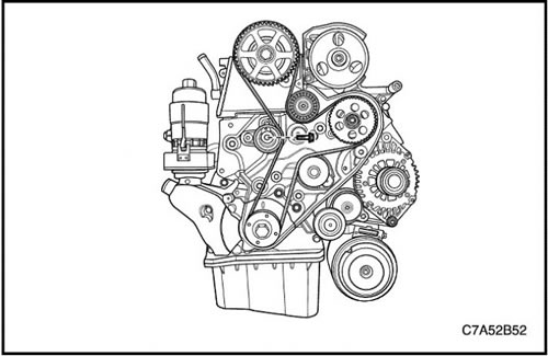
5. Remove the cylinder head cover. See "Cylinder head cover" in this section.
6. Remove the timing belt. See "Timing Belt Drive System" in this section.
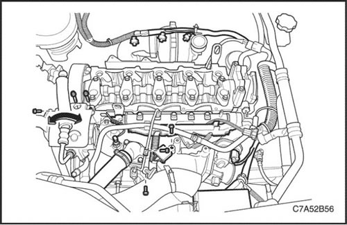
7. Remove the common rail fuel line located between the common rail and the fuel injection pump. See Section 1F1, Engine Controls - 2.0 Diesel.
8. Remove the power steering pump fastener and move it to the left side.
9. Loosen the tightening bolt of the engine wire connector block.
10. Remove the oil level indicator tube.
11. Remove the upper radiator hose from the thermostat housing.
12. Remove the engine wiring connectors.
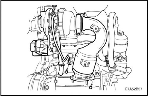
13. Remove the oil supply pipe to the turbocharger impeller bearing.
14. Remove the oil drain hose from the turbocharger impeller bearing.
15. Remove the pre-catalytic converter clamp from the turbocharger.
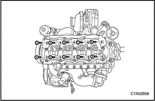
16. Remove the cylinder head bolts.
17. Remove the cylinder head assembly with the gasket.
18. Remove the intake manifold and exhaust manifold from the cylinder head assembly. See "Intake Manifold" and "Exhaust Manifold" in this section.
Cleaning procedure
1. Clean the surface of the cylinder head.
2. Clean the surface of the engine cylinder block.
3. Clean the cylinder head bolts.
4. Clean the engine block bolt holes.
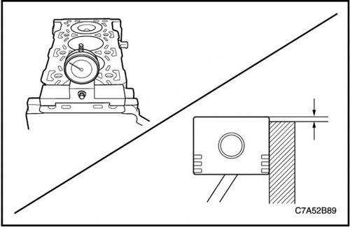
Select a gasket
1. Set the piston to TDC.
2. Clean the sealing surface of the cylinder head and piston.
3. Measure the piston protrusion with a dial indicator.
4. Repeat this measurement on other cylinders and calculate the arithmetic mean value of piston protrusion based on the measurement results.
5. Select a cylinder head gasket based on the specifications below.
| Piston protrusion, mm | Gasket thickness, mm |
| 0,194...0,337 | 1.1 |
| 0,337...0,440 | 1,2 |
| 0,440...0,542 | 1.3 |
Installation procedure
1. Install the cylinder head assembly with a new gasket.
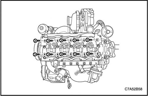
2. Tighten the cylinder head clamp bolts.
Tighten
Tighten the cylinder head bolts to 65 Nm (47.9 ft·lbs). Using the KM-470-B angular torque gauge, tighten the cylinder head bolts an additional 120 degrees plus 120 degrees.
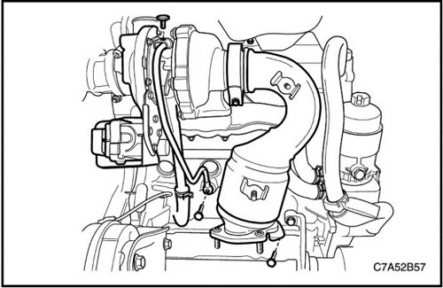
3. Install the pre-catalytic converter clamp onto the turbocharger.
4. Install the oil feed pipe into the turbocharger impeller bearing.
Tighten
Tighten the turbocharger impeller bearing oil feed pipe bolts to 23 Nm (17 ft·lbs).
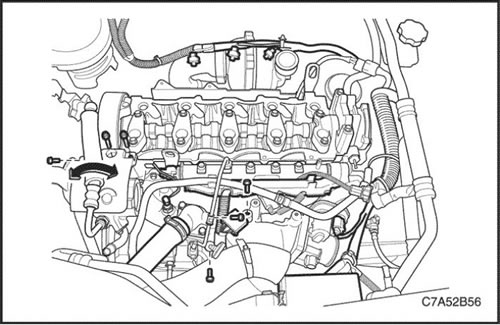
5. Tighten the engine wire connector clamp bolt.
6. Install the power steering pump bracket.
7. Install the fuel line to the common rail located between the common rail and the fuel injection pump.
8. Install the oil level indicator tube.
Tighten
Tighten the engine wiring harness connector clamp bolt to 15 Nm (11.1 ft·lbs).
Tighten the steering pump bolts to 25 Nm (18.4 ft·lbs).
Tighten the fuel line fastening nut to the common fuel rail to 20 Nm (14.8 ft·lbs).
Tighten the bolt securing the fuel line to the common fuel rail to 10 Nm (88.5 lbs.in).
Tighten the oil level indicator tube bolts to 11 N·m (97.4 lbs.in).
(The source of the article is available on the website: ChevyMan.ru)